5 installing the remote management module 2, 1 installing the gcm module, 2 installing the rmm2 – Kontron NSW1U IP Network Server User Manual
Page 55: Installing the remote management module 2 4.5.1, Installing the gcm module, Installing the rmm2
Kontron IP Network Server NSW1U
December 2009
Product Guide, rev. 1.4
55
Optional Component Installation Procedures—NSW1U Network Server
4.5
Installing the Remote Management Module 2
To install the GCM module and the Intel
®
Remote Management Module 2 (Intel
®
RMM2), you must
first remove the chassis top cover, the processor air duct, and PCI riser card assembly. For
Chapter 3, “Server Installations and Upgrades”
and
PCI Riser Card Assembly” on page 52
.
4.5.1
Installing the GCM Module
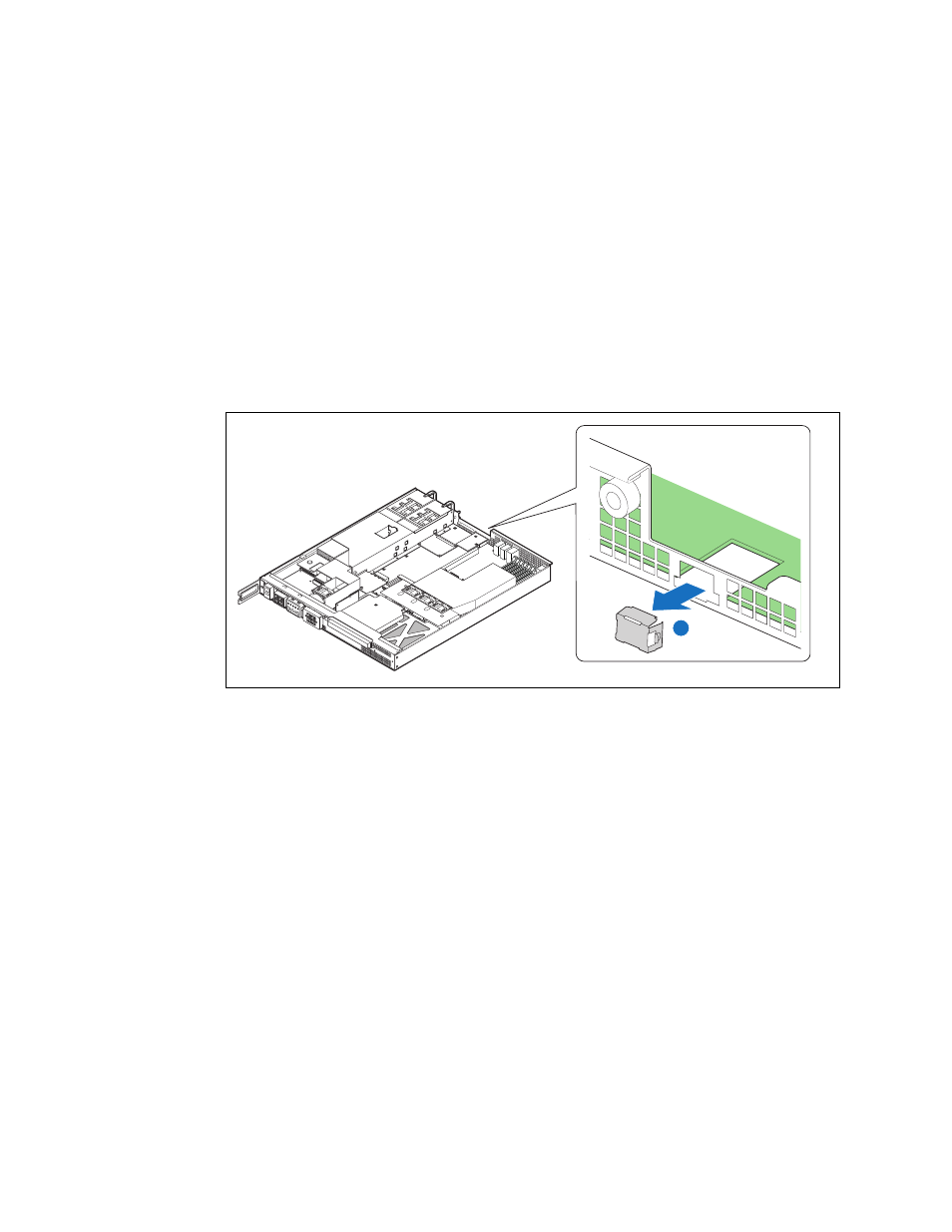
1. Remove the filler panel from the rear panel of the chassis by squeezing the side edges and
pushing it out from inside the chassis. (
, “A”)
2. Snap the two standoffs into the S5000PHB server board server board. (
, “C”)
3. Attach the GCM module to the server board using the connector. (“D”)
4.5.2
Installing the RMM2
1. Insert the standoff into the hole labeled “TH4” on the RMM2. (
, “A”)
The standoff fastens to the bottom side of the module.
2. Fasten the RMM2 to the S5000PHB server board site using the Advanced Server Management
Interface (ASMI) connector (“B”) and snap the standoff into the matching hole in the server
board.
3. If this is the last task you are performing, replace the riser card assembly, the processor air duct,
and the top cover of the chassis. Reconnect all the external devices and plug in the power cord(s).
Figure 36.
Removing the GCM Port Filler Panel
A
TS000413