Can connector – Kontron Micro Client 3 104 User Manual
Page 61
10. Standard Interfaces – Pin Assignments
Micro Client 3 – User’s Guide (Version 1.0)
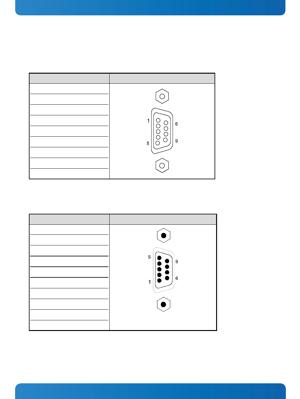
10.1.5. Serial Port (RS422/RS485) configured as RS485 (2-Wire Mode), half duplex
Refer to the chapter 7.3.1 “RS422/RS485 Serial Interface Connector/s”, Table 1, Table 2 and Table 3.
Pin Signal Name
9-pin D-SUB Connector (female)
1
Data-
2
NC
3
Data+
4
NC
5
GND (Signal Ground)
6
NC
7
NC
8
NC
9
NC
10.1.6. CAN Connector
Refer to the chapter 7.3.2 “DIP-Switch Settings (SW1) for LPCtoCAN Adapter”.
Pin Signal Name
9-pin D-SUB Connector (male)
1
NC
2
CANL (galavic separated)
3
CAN0V (galavic separated)
4
NC
5
NC
6
NC
7
CANH (galavic separated)
8
NC
9
NC
case GND
www.kontron.com
59
This manual is related to the following products: