Bottom view, Fig. 19: bottom view of the mc 3 104, Fig. 20: bottom view of the mc 3 156 – Kontron Micro Client 3 104 User Manual
Page 24
7. Product Description
Micro Client 3 – User’s Guide (Version 1.0)
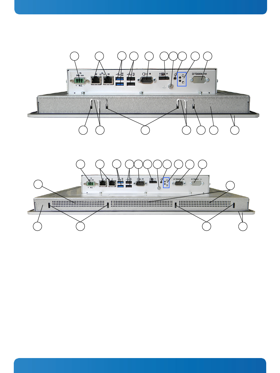
7.2. Bottom View
Fig. 19: Bottom view of the MC 3 104
Fig. 20: Bottom view of the MC 3 156
Legend for
and
1 DC power connector
2 2x Ethernet connector (RJ45) 10/100/1000 Mbps)
3 2x USB (3.0) connector (blue)
4 2x USB (2.0) connector
5 1x COM1 (RS232) serial port connector (DSUB, 9-pin)
6 1x DisplayPort
7 Grounding screw with lock washers
8 Power button
9 LED indicators (power and HDD)
10 Optional interface (CAN-BUS and/or RS422/485 interfaces
for MC 3 104/121/150/170 and MC 3W 156)
11 Display enclosure
12 Front panel of the system with seal at the rear side
13 Mounting slots for mounting clamps
14 Small mounting clamp with Allen screw (shown for the
MC 3 104)
15 Air openings on the display side
13
13
11
14
12
1
4
5
8
10
2
3
9
6
7
15
13
11
15
12
13
10
1
4
6
5
9
2
8
3
13
14
7
10
22
www.kontron.com