Interfaces (rear, bottom side of the system), Lan0 and lan1 ethernet interface connectors, Usb connectors – Kontron Micro Client 3 104 User Manual
Page 28: Displayport interface connector, Com1 serial interface connector
7. Product Description
Micro Client 3 – User’s Guide (Version 1.0)
7.2.3. Interfaces (Rear, Bottom Side of the System)
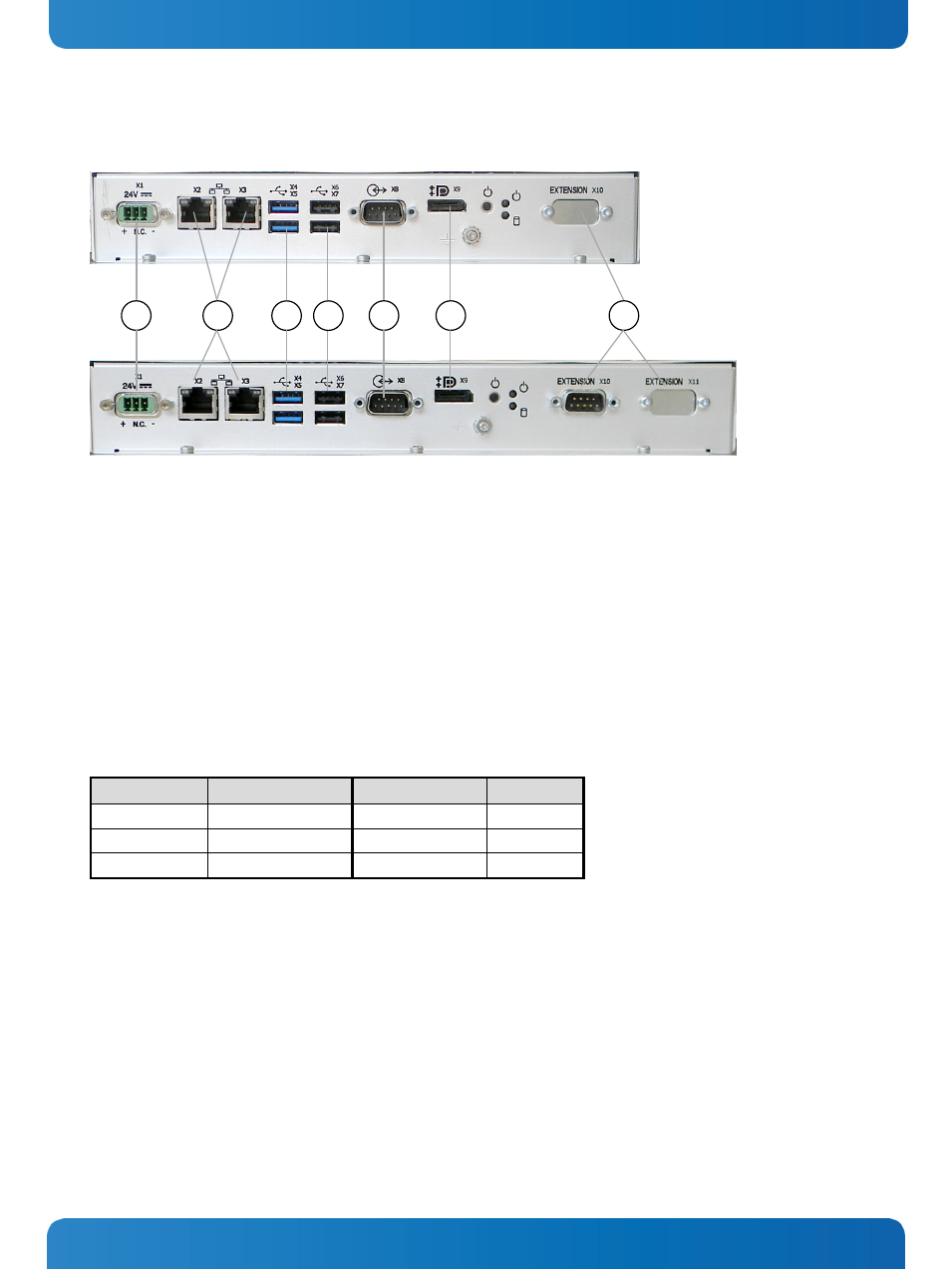
Fig. 25: Detail with interfaces for MC 3 104 system
Fig. 26: Detail with interfaces for MC 3 121/150/170 and MC 3W 156 systems
Legend forFig. 25 and Fig. 26:
1 DC power connector
2 2x LAN (1Gbps) connector
3 2x USB 3.0 connector
4 2x USB 2.0 connector
5 COM1 (RS232) serial port connector
6 Display Port connector
7 Optional interfaces (shown as CAN-BUS for
MC 3W 156 system)
7.2.3.1.
LAN0 and LAN1 Ethernet Interface Connectors
These interface connectors (Fig. 19,
, pos. 5 and Fig. 25, Fig. 26 pos. 2) are provided as RJ45 sockets with integrated
LEDs and support a 10/100/1000 Mbps data transfer rate.
Ethernet LED States:
Left LED State
Link Activity State
Right LED State
Link Speed
off
Link not active
Off
10 Base-T
yellow
Link active
green
100 Base-T
yellow (blinking) Link active
green (flashing)
1000 base-T
7.2.3.2.
USB Connectors
The system is equipped at the bottom side (rear) with two USB 2.0 and two USB 3.0 interface connectors (Fig. 19,
pos. 3, pos. 4 and Fig. 25, Fig. 26 pos. 3, pos. 4). These connectors provide connections for USB-compatible devices.
7.2.3.3.
DisplayPort Interface Connector
An external (digital) monitor can be plugged into this interface (Fig. 19,
, Fig. 25 and Fig. 26 pos. 6).
7.2.3.4.
COM1 Serial Interface Connector
This RS232 connection (marked as COM1) (Fig. 19,
, pos. 4 and Fig. 25, Fig. 26 pos. 5) are available as 9-pin D-SUB
connectors (female) and provides connection (RS232) for serial devices.
1
2
6
5
7
3
4
26
www.kontron.com