Power and grounding, Dc in power connector, Grounding screw (m4) with lock washers – Kontron Micro Client 3 104 User Manual
Page 25
7. Product Description
Micro Client 3 – User’s Guide (Version 1.0)
In the MC3 121/150/170 and MC 3W 156 systems up to three different modules for (RS422/485) or RS232
or CAN-BUS interfaces can be installed.
In the MC 3 104 systems two modules for (RS422/485) or RS232 or CAN-BUS interface can be installed.
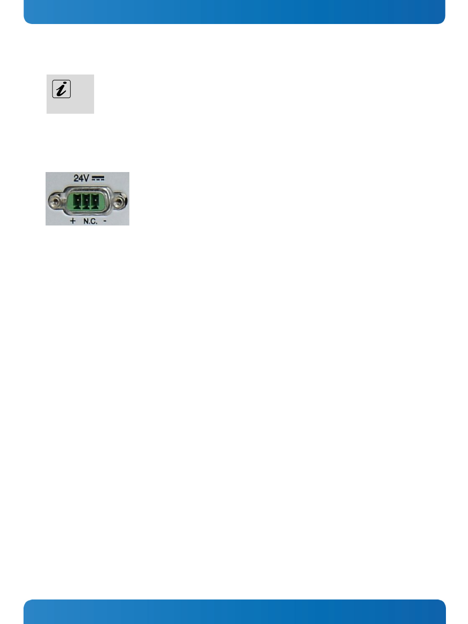
7.2.1. Power and Grounding
7.2.1.1.
DC In Power Connector
Fig. 21: Detail of the DC Power connector shown without Phoenix terminal
The MC 3/MC 3W system is supplied with a 3-pin Phoenix power connector terminal (refer to Fig. 40). The DC Power
connector (Fig. 21) provides the power connection of the
MC 3/MC 3W system to the main power source via a DC power
cable (not included). For pin-assignment of this connector refer to the chapter 10.1.1 “Power Connector”.
7.2.1.2.
Grounding Screw (M4) with lock Washers
The chassis of the MC 3/MC 3W system must be grounded by establishing a
large-area contact between the grounding stud
M4x10 (DIN7985) with 2x lock washer M4 (DIN6797) and nut M4 (Fig. 19, Fig. 20, pos. 7, and Fig. 22, pos. 4), and an
appropriate grounding connection point. The minimum cross section of the grounding conductor is 1mm
2
(AWG 18).
www.kontron.com
23