Top view, D fig. 30, fig. 31, D fig. 30 – Kontron Micro Client 3 104 User Manual
Page 33: D fig. 31
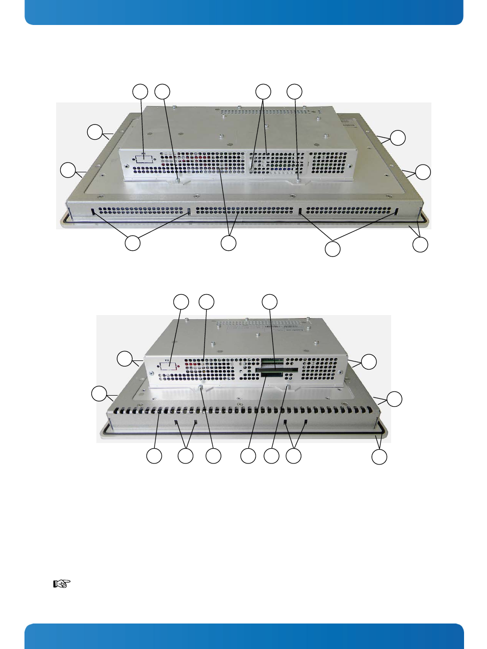
7. Product Description
Micro Client 3 – User’s Guide (Version 1.0)
7.4. Top View
Fig. 30: Top side of the system (shown as MC 3W 156, with CF/SD card slot cover attached)
Fig. 31: Top side of the system (shown as MC 3 104, with CF/SD card slot cover removed)
Legend for Fig. 30 and Fig. 31:
1 CF/SD card slot cover with captive screw
2 CompactFlash™ slot (with CF card)
3 SD card slot
4 Air exhaust openings
5 Screws that secure the cover on the top side
6 Front panel with seal on the rear side
7 Mounting slots for mounting clamps
8 Cutout for optional interfaces
When powering on the MC 3 system, make sure that the air intake and exhaust
openings are not obstructed.
7
6
5
1
2
4
6
7
7
7
5
8
8
4
5
7
4
5
3
7
7
7
7
7
7
7
www.kontron.com
31