Elecraft T1 Assembly Manual User Manual
Page 9
9
Main PC Board Assembly Procedure – Part I
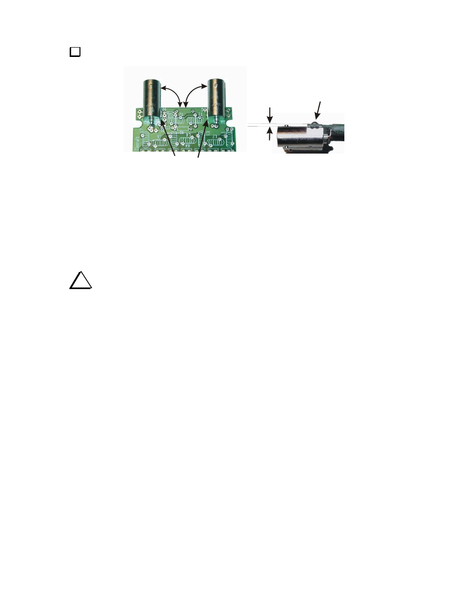
Install BNC connectors J1 and J2 as follows. When completed they must be aligned as shown
in Figure 3.
JACKS CENTERED
WITHIN
PRINTED OUTLINES
USE HEAVY-DUTY
IRON TO SOLDER
MOUNTING NUBS
(SEE TEXT)
90
O
JACK BARRELS
PARALLEL WITH
BOARD
Figure 3. Installing J1 and J2.
__ Position BNC connector J1 on the board over the printed outline as shown with the mounting nubs and
center connector passing through the holes provided. Be certain the barrel is at a 90-degree angle with the
edge of the board and parallel to the board as shown in Figure 3.
__ While holding the connector in place, wet the tip of your iron with a drop of solder and use it to
temporarily tack-solder the connector center terminal.
__ Check to ensure the connector is still aligned as shown in Figure 3. If not, re-heat the tack soldered joint
and adjust the position. It will be very difficult to adjust the connector after you complete the next step.
i
In the following step you will use a large iron to solder the two mounting nubs on the BNC
connector to the board. This is the only time you should use anything other than a temperature-
controlled, ESD-protected soldering station to assemble your T1 tuner.
__ Place the board the bottom side up on a surface that will not be damaged if body of the BNC connector
becomes warm. Apply the large iron and solder to the end of one amounting nub where it protrudes through
the circuit board. Remove the iron as soon as the solder flows onto the pad. Do not put the iron directly on
the solder pad. Do not be concerned if solder fills the pad marked G near J1.
__ Solder the second mounting nub using the same procedure.
__ Using your temperature-controlled iron, properly solder the center pin that you tack-soldered earlier.
__ Repeat the above procedure to install the second BNC connector, J2.