Elecraft T1 Assembly Manual User Manual
Page 11
11
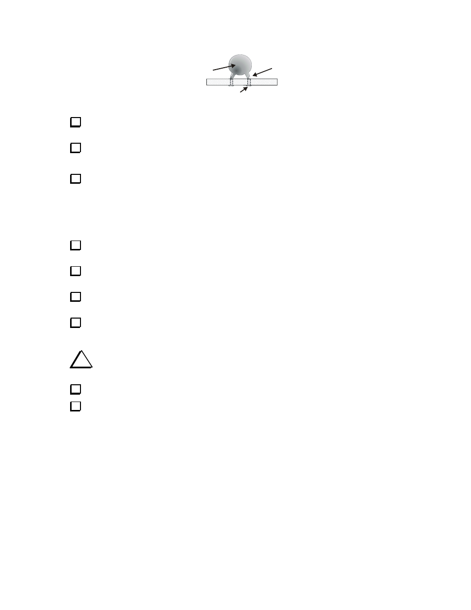
SOLDER & TRIM LEADS.
10
THE NUMBERS IN PARENTESIS
IN THE TEXT MUST APPEAR ON
THE BODY. USUALLY THERE
ARE OTHER MARKINGS AS WELL.
GENTLY FORM LEADS SO
CAPACITOR SITS AS CLOSE
TO THE BOARD AS THE
INSULATION ALLOWS.
Figure 5. Installing Capacitors.
Bend the leads out at 45-degree angles on the bottom side of the board to hold the capacitor in place,
then solder and trim the leads flush with the bottom of the board.
Install the following capacitors in the outlines shown across the center of the PC board adjacent to C1.
__ C2, 20 pF (20)
__ C3, 39 pF (39)
__ C4, 82 pF (82)
Install the following capacitors in the outlines shown across the next to the ones you just installed. Be
careful to insert the leads in the correct solder pads. There are solder pads very close to those for C5 and C7
for two capacitors that will be installed on the bottom of the PC board later. Make sure you don’t use these
pads by mistake. Also, be sure the larger capacitors are positioned so they do not overlap the outlines for
the relays on either side.
__ C5, 150 pF (151)
__ C6, 330 pF (331)
__ C7, 330 pF (331)
Install capacitor C10, .001 µF, LS 0.1” (102) in the outline at the end of the PC board farthest from
BNC connectors J1 and J2. Look closely at the marking. Do not use (105) my mistake.
Locate diode D1 (1N5711). You may need to use a strong magnifier to read the numbers. The
numbers are often printed on the body in two rows of three letters each (e.g. 1N5 and 711)
Locate the outline for D1 on the circuit board near J2 and R1. Note that the printed outline has a band
near one end.
Gently bend D1’s leads at right angles to the body and insert it into the solder pad holes with the
banded end of the diode toward the banded end on the printed outline. On the bottom of the board, bend the
leads at 45 degree angles to hold it in place.
i
Your T1 tuner will not operate correctly if the banded end of the diode is not aligned with the
banded end of the outline on the PC board.
Solder the leads and trim them flush.
Install diode D2 (1N5711) the same way you installed D1. D2 is close to BNC connector J2.