Elecraft T1 Assembly Manual User Manual
Page 16
16
Main PC Board Assembly Procedure – Part II
i
In the following steps you’ll wind and install the toroidal transformers and inductors. They
must be wound on the correct toroid core exactly as described or your tuner will not operate
properly.
1
Wind transformer T1 as follows:
__ Locate an FT37-43 toroid core. This is a dark grey core that is not painted. There are three of them in
the kit.
__ Cut a 7-inch (18 cm) length of the red enameled wire.
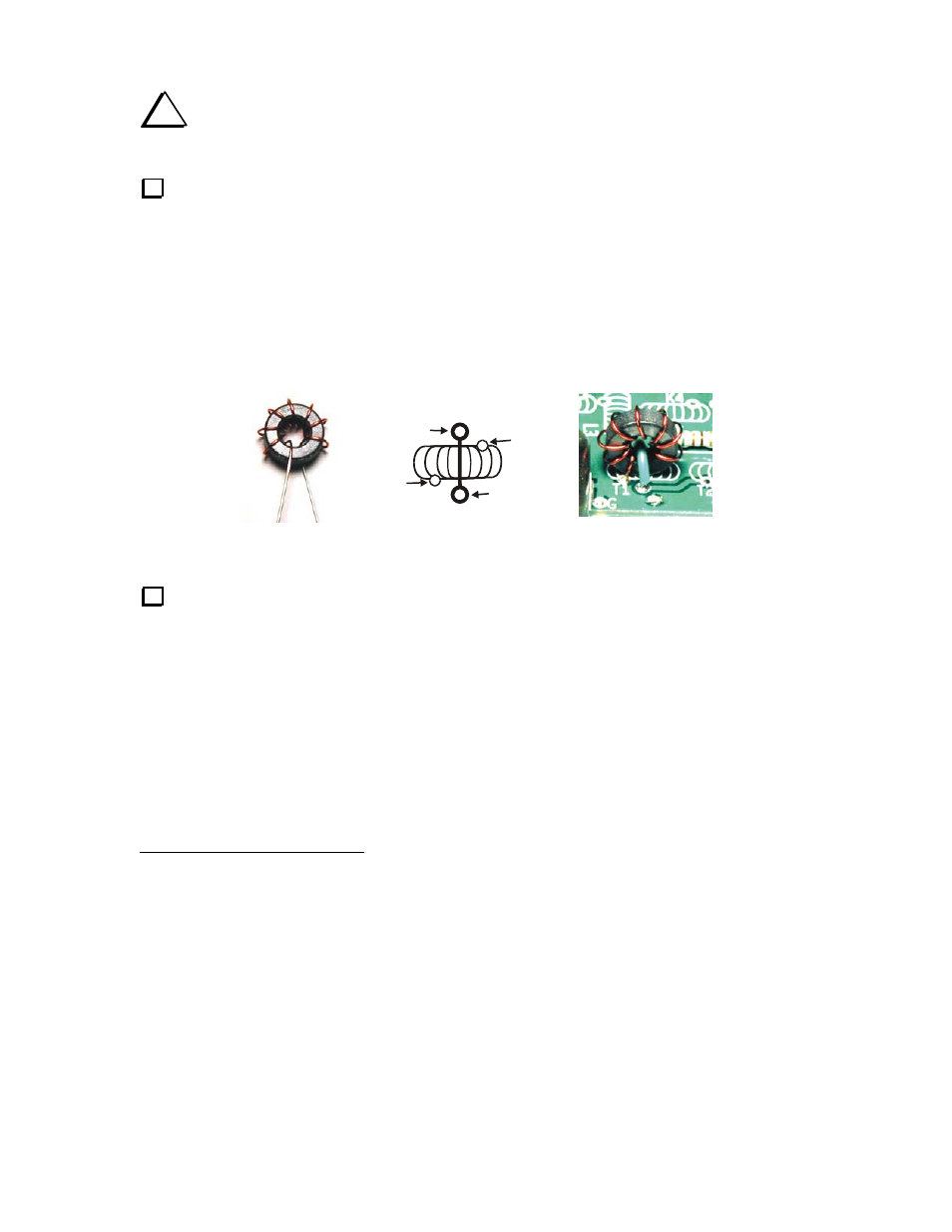
__ “Sew” the long end of the wire through the hole in the core for a total of 8 turns. Count one turn each
time the wire passes through the center of the core. There are no half or quarter turns when winding a
toroid. Match the winding direction shown in Figure 8 so the leads will line up with the solder pads on
the circuit board.
__ Spread the turns around the core as shown in the figure.
T1 READY FOR
INSTALLATION
LEAD POSITIONS
ON PC BOARD
T1 INSTALLATION
COMPLETE
SMALLER
SECONDARY
LEAD
GREEN
PRIMARY
LEAD
GREEN
PRIMARY
LEAD
SMALLER
SECONDARY
LEAD
Figure 8. Transformer T1.
Strip the insulation and tin the leads using one of the following methods. Strip off the enamel all the
way up to the core. It will not hurt performance if the tinned area of the lead touches the core.
1. Heat stripping: Melt a blob of solder on the tip of your iron and insert the clipped end of the lead
in the blob. The insulation will bubble and vaporize after about 5 seconds. Add solder and feed the
wire into the blob up to the edge of the core, then slowly pull the wire out of the solder. If any
enamel remains on the lead, scrape it away.
2. Burn the insulation off by heating it with a butane lighter for a few seconds. Remove any residue
with sandpaper, then tin the bare wire.
3. Scrape the wire with a sharp tool. Take care not to nick the wire. Remove all the insulation around
the entire circumference of the wire, then tin the wire.
1
Prewound toroids are available from an Elecraft-approved source. See www.elecraft.com for details.