Elecraft T1 Assembly Manual User Manual
Page 19
19
Visual Inspection
Use a magnifier and good light to check the board for the following:
Missed solder connections. Look closely at each relay pin.
Solder bridges. Look closely at the SMD capacitors between the relay pins.
Properly tinned toroid leads. You should see some tinned lead above the PC board on every toroid. Be
suspicious of any leads where the enameled part of the wire goes into the solder pad. If in doubt, remove,
clean and tin more of the lead or rewind the toroid.
Diode orientation. The banded ends of D1 and D2 must be nearest BNC connector J2.
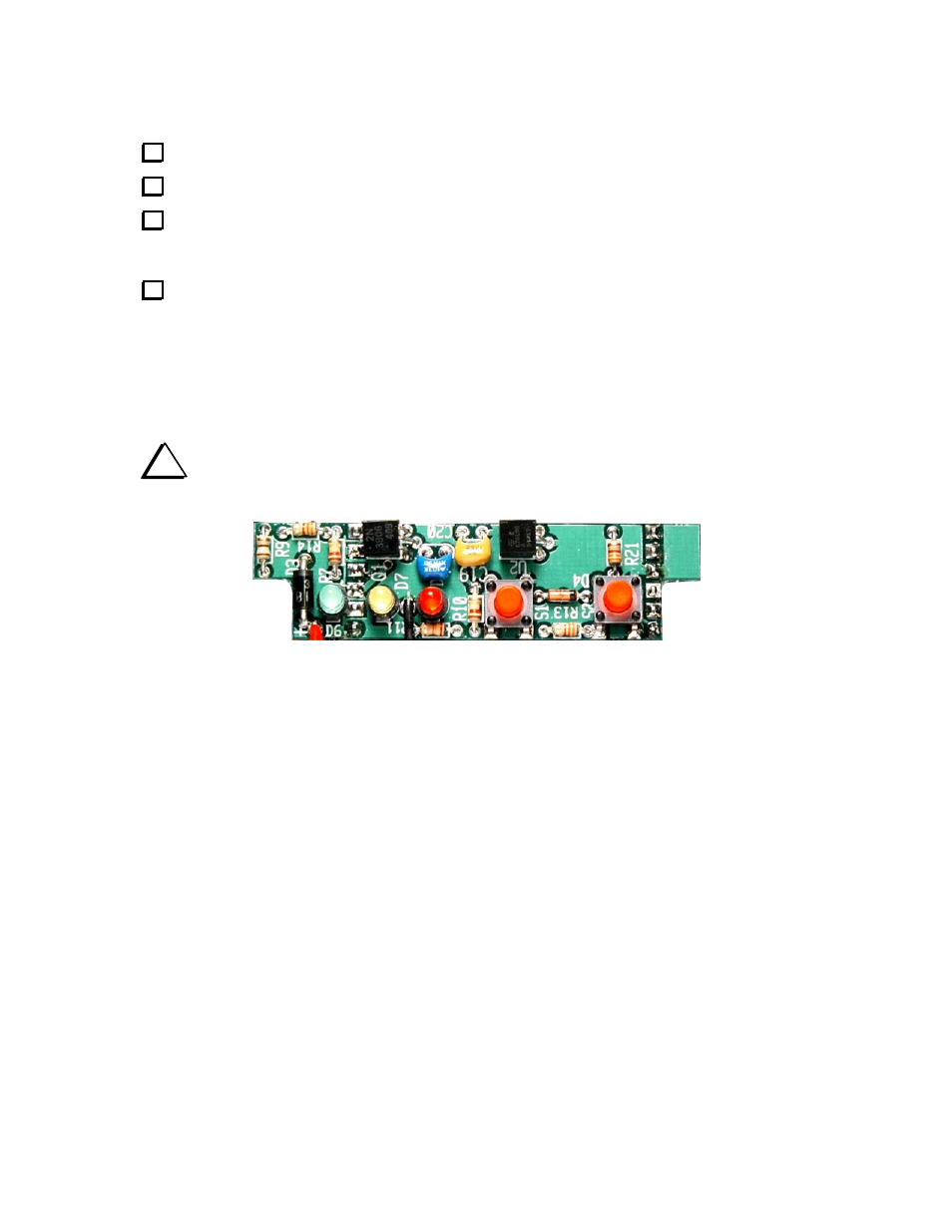
Control Board Assembly
The completed control PC board is shown in Figure 12. All of the components are mounted on the top of
the board. There is very little excess space above or below this board when your tuner is assembled in its
enclosure. Follow the instructions carefully to ensure the board will fit when you assemble your tuner.
i
It is almost impossible to remove a part without destroying the part or damaging the board.
Double-check the position and value of all parts installed on the control board before soldering.
Figure 12. Completed Control PC Board.