Elecraft T1 Assembly Manual User Manual
Page 10
10
i
Use only your temperature-controlled, ESD-protected soldering station for the remainder of
the assembly.
Bend the leads for R1, 51 ohms (grn-brn-blk or 510J), 1 watt, at right angles to the body. Insert the
leads in the solder pad holes at the ends of the printed outline between J1 and J2. There are three holes very
close together at the end of R1 near J2. Be sure the leads go through the proper holes in the board, indicated
by short white lines on the part outline. On the bottom side of the board, bend the leads out at 45-degree
angles to hold the resistor in place.
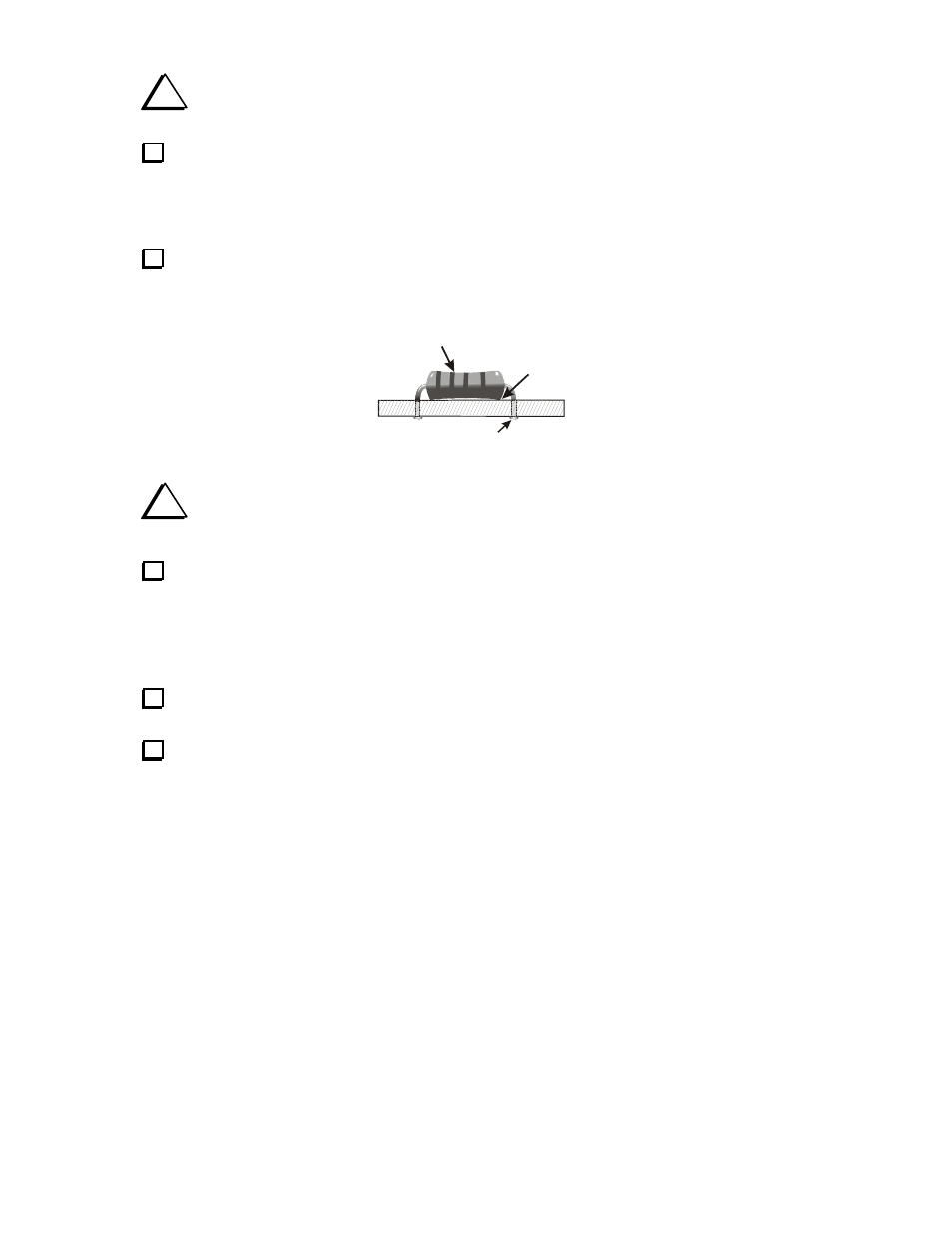
Check the position of the resistor to be sure it is centered in the printed outline and flush against the
board as shown in Figure 4. Solder, taking care not to get solder in either of the empty holes at the J2 end of
the resistor. Trim the leads flush with the bottom of the board.
BODY OF PART
AGAINST THE BOARD
ENSURE MARKINGS AGREE WITH
INSTRUCTIONS IN TEXT
SOLDER & TRIM LEADS FLUSH
Figure 4. Installing Resistors.
i
From this point forward, instructions to “install” a component mean to position it within its
outline against the board, solder and trim the leads flush on the opposite side.
Install the following resistors in the outlines shown at the end of the PC board opposite BNC
connectors J1 and J2. These resistors are 1/8 watt resistors, about half the size of R1.
__ R5, 120K (brn-red-yel) 1/8 W
__ R6, 120K (brn-red-yel) 1/8 W
__ R3, 3.3K (org-org-red) 1/8 W
__ R4, 3.3K (org-org-red) 1/8 W
Locate capacitor C1, 10 pF (10). Note that the capacitors may have markings on their bodies in
addition to the value given in parenthesis.
Insert C1 into the holes in the outline on the PC board. With the BNC connectors toward you, the
position for C1 is about half way back on the left edge. If necessary, gently straighten the leads so the
capacitor will sit close to the board without excessive lead lengths as shown in Figure 5. When
straightening the leads, do not tug on them. Squeeze and bend the leads with your pliers to straighten them.
Chipping of the insulation around the leads will not harm the capacitor.