Elecraft T1 Assembly Manual User Manual
Page 15
15
Inspect the assembly to be certain the control PC board is oriented as shown in the figure. The top of
the board should be level with and slightly below the top of the relays next to it. The connectors must be
square against the two boards. If necessary, reheat the soldered pins and adjust the connectors. The
assembly must be as shown for the tuner to fit in its enclosure properly.
Solder all the pins on P1, P2 J4 and J5. At P1, be careful not to create a solder bridge between
pin 3 and the solder pad for resistor R4 that is very close.
Unplug the control PC board and set it aside.
On the bottom side of the board between BNC connectors J1 and J2, install resistor R2, 51 ohms
(grn-brn-blk or 510J), 1 watt. Trim the leads flush with the top of the board.
Install C7A on the bottom of the board as follows:
__ On the bottom side of the board, locate the outline for capacitor C7A.
__ Insert the leads for C7A, 330 pF (331) through the solder pads and fold the capacitor down flat against
the board toward the edge. Orient it so you can read the value. Do not solder yet!
__ Remove C7A and pre-trim its leads so they pass through the solder pads but do not protrude through the
top side of the board. If necessary, remove a small amount of the insulation from around the leads near the
capacitor body to expose the lead and solder pad.
__ Solder C7A in place from the bottom of the board.
Install C5A, 10 pF (10) on the bottom of the board in the same way you installed C7A. Fold C5A
toward the pins of K14 at the center of the board.
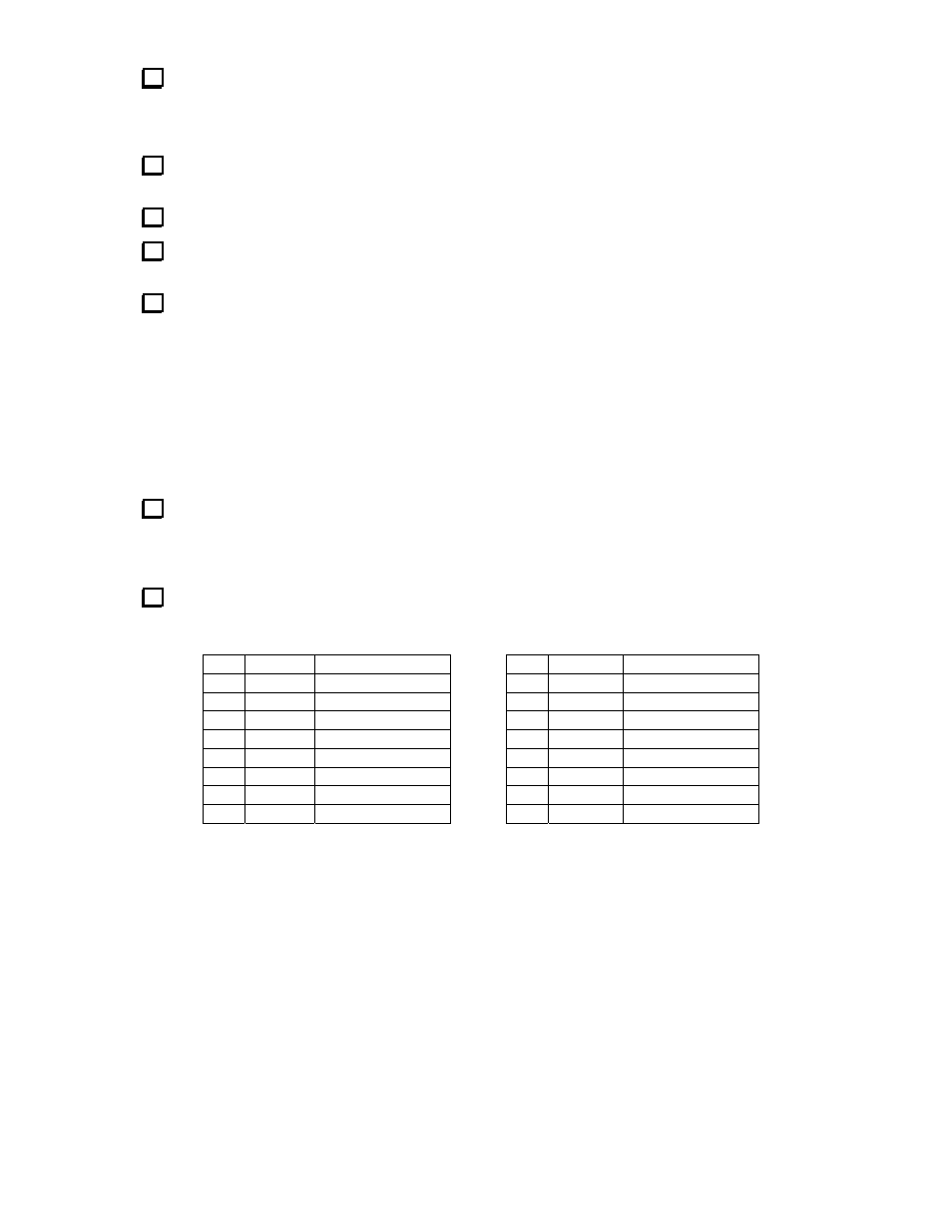
Resistance Checks
Make the following resistance checks between the various pins of socket U1. Pin 1 is nearest the edge
of the board at the end near the stereo jack. Count down the row, across the end and back up the other side.
Pin 28 is across from pin 1 at the end near the stereo jack.
√
U1 Pins
Resistance
√
U1 Pins
Resistance
4 – 11
400 – 420 ohms
4 – 23
400 – 420 ohms
4 – 12
400 – 420 ohms
4 – 24
400 – 420 ohms
4 – 13
400 – 420 ohms
4 – 25
400 – 420 ohms
4 – 14
400 – 420 ohms
4 – 26
400 – 420 ohms
4 – 15
400 – 420 ohms
4 – 27
400 – 420 ohms
4 – 16
400 – 420 ohms
4 – 28
400 – 420 ohms
4 – 21
400 – 420 ohms
20 – 8
> 100 k or Inf.
4 – 22
400 – 420 ohms
10 – 8
> 100 k or Inf.