Elecraft T1 Assembly Manual User Manual
Page 17
17
i
The leads must be stripped of insulation and tinned correctly to provide good electrical
contact when installed. Carefully inspect each tinned lead for:
A clean, tinned lead with no enamel residue left under the tinning.
The lead must be tinned all the way around the wire.
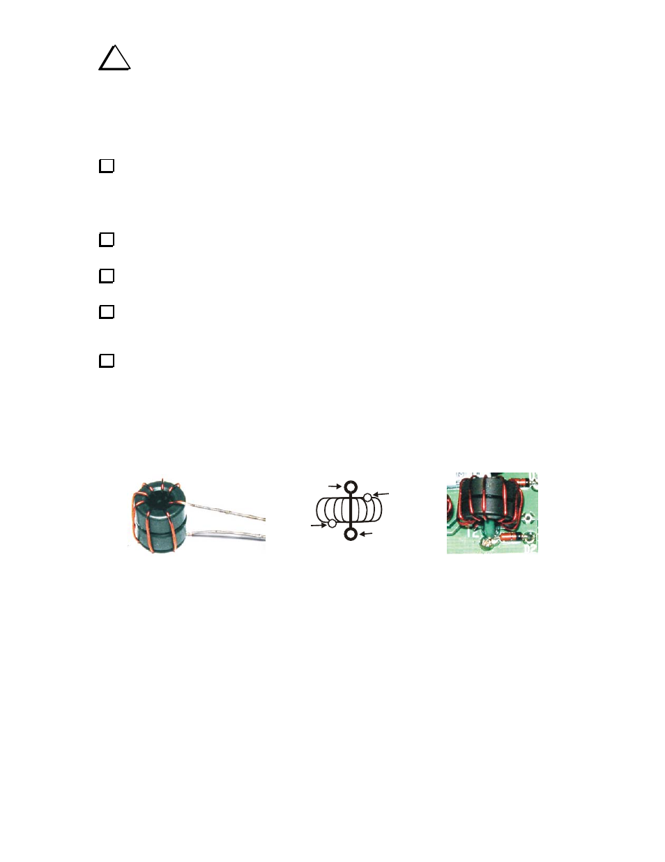
The lead should be tinned all the way up to the core as shown in Figure 8.
Locate the outline for T1 between BNC connectors J1 and J2 on the PC board. Thread the tinned leads
of T1 through the smaller pads (See Figure 8). Position the toroid over the outline as shown and bend the
leads on the bottom of the circuit board to hold the toroid against the PC board in place. Inspect the lead on
the top side of the board to be sure tinned lead is visible above the solder pad. If not, remove the toroid,
clean and tin the lead closer to the core and replace it on the PC board.
Solder and trim both leads flush, then adjust the position of T1, if needed, so it sits within the outline
printed on the PC board.
Cut a 3/4” (19 mm) length of the green insulated solid wire. Strip the insulation from 1/4” (6 mm) at
each end of the wire.
Thread the wire through the center of T1 and into the holes on either side of the printed outline for T1
on the PC board to form the 1-turn primary winding for the transformer. Solder and trim the wires flush
with the bottom of the board.
Transformer T2 is identical to T1 except that it uses two FT37-43 cores stacked together as shown in
Figure 9. To simplify winding the secondary, you may wish to glue the cores together using epoxy or
cyanoacrylate adhesive (super glue). Prepare and install transformer T2 using:
_
15” (39 cm) of red enamel wire for the secondary and wind 8 turns (wire passes through the
center 8 times).
_
1” (25.4 mm) of green insulated wire for the primary winding. Strip 1/8” (3mm) from each end.
Because of the tight fit, you may find it easier to prepare the green primary wire, loop it through the toroid,
then insert the secondary leads and the green primary leads into the pc board pads at the same time.
T2 SECONDARY WOUND
ON TWO FT37-43 CORES
T2 INSTALLATION
COMPLETE
BE CERTAIN THE LEADS ARE INSTALLED
IN THE CORRECT PC BOARD PADS
SMALLER
SECONDARY
LEAD
GREEN
PRIMARY
LEAD
GREEN
PRIMARY
LEAD
SMALLER
SECONDARY
LEAD
Figure 9. Transformer T2.