Elecraft T1 Assembly Manual User Manual
Page 14
14
On the top of the board, position ceramic resonator Z1 (4.00 MG) in the outline between the socket for
U1 and the edge of the board. Even though it may have a red dot on one end, the resonator may be installed
in either direction. Hold the resonator so the insulation on the leads is against the top of the board, then
tack-solder one pin. Verify that the insulation of all three leads is against the top of the board. If it is
allowed to sit too high it will strike the control board when you assemble the tuner.
Solder all three pins on Z1.
Position the miniature stereo jack in the outline for J3 on the top of the board. The round portion of the
jack will extend over the edge of the board. Hold the jack against the board and tack-solder one pin. Verify
that the jack is solidly against the board, otherwise it may not line up with the hole in the enclosure when
you assemble your tuner.
i
Use no more solder than is necessary for a good joint on J3. Filling the holes with too much
solder may allow it to flow into the jack and ruin it.
Solder all three pins on J3.
Locate the two 6-pin male connectors, P1 and P2, that you just test-fitted on the board, and the two
6-pin female connectors J4 and J5.
Insert the longer pins of the male connectors into the female connectors. Be sure the connectors are
fully mated. There may be a small gap remaining between the plastic parts.
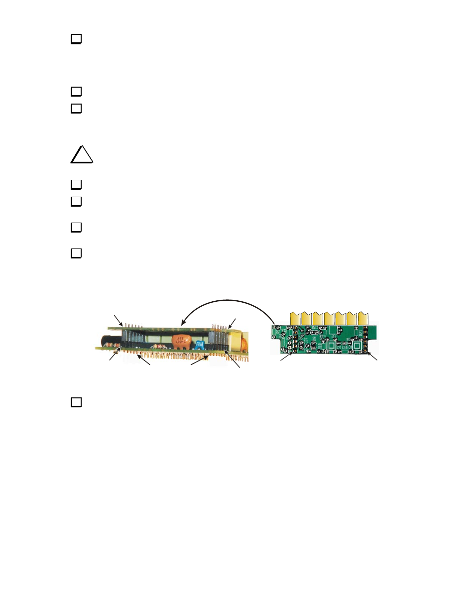
Refer to Figure 7. Place the pins of P1 and P2 into position at each end of the 28-pin socket on the
main PC board, then place the control PC board on the pins of J4 and J5 as shown. Be sure the control
board is oriented with the top side shown in the figure facing up. The ends of the control board should line
up with the sides of the main PC board. The notched corners must be over the cutouts near the corners of
the main PC board.
J4
J5
J5
SHORT PINS
P2
P1
THIS SIDE MUST FACE UP
RELAYS ON MAIN PCB
J4
Figure 7. Installing P1, J4, P2 and J5.
Hold the assembly and tack-solder one terminal on P1, P2, J4 and J5. Do not to touch the relays with
your soldering iron.