Fig. 60, Fig. 59, Fig. 57 – EFCO 904 Series User Manual
Page 50: Fig. 58
FOR MORE DETAILED STEPS, PART # Y015.
SEE THE DOOR AND HARDWARE INSTALLATION INSTRUCTIONS
JDA 3/2002
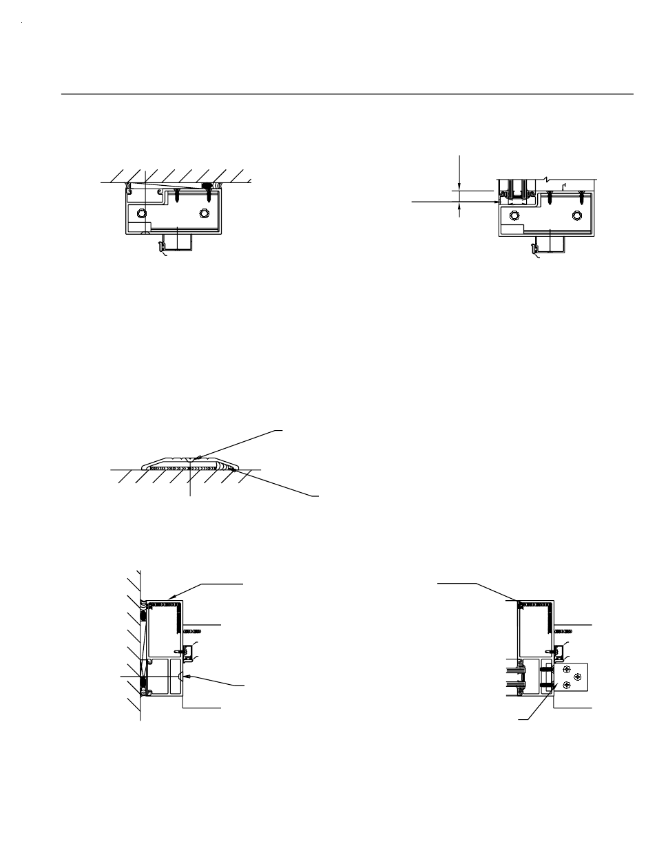
screws, located 6" from
At condition, attach through
the header with flat head
maximum spacing.
the ends and 24" on center,
Attach through the threshold with flat head screws.
at the condition.
DOOR JAMB SET IN SEALANT
ANCHOR THROUGH THE JAMB
the back of the threshold and sides of the
Continuous bead of sealant at
jambs, and tied into mullion sealant
12" from jambs and 12" on center max.
AT THE DOOR LOCATION.
[FIG. 60]
9154/9155
W138
[FIG. 59]
EXTERIOR
INTERIOR
[FIG. 57]
W138
K273 RH
K274 LH
9593
9914
CLIP
THRESHOLD
FRAMING
SIDE LITE
9154/9155
W138
9914
[FIG. 58]
W138
9593
K274 LH
K273 RH
(CONT.)
SECTION VI A - DOOR FRAME INSTALLATION
PAGE 48
1/4" Dia. Weep
at 1/4 Points
5/8"
Quick Set