Fig. 29, Step 4) [fig. 28, Step 3) – EFCO 904 Series User Manual
Page 32: 2 pc. jamb and intermediate verticals
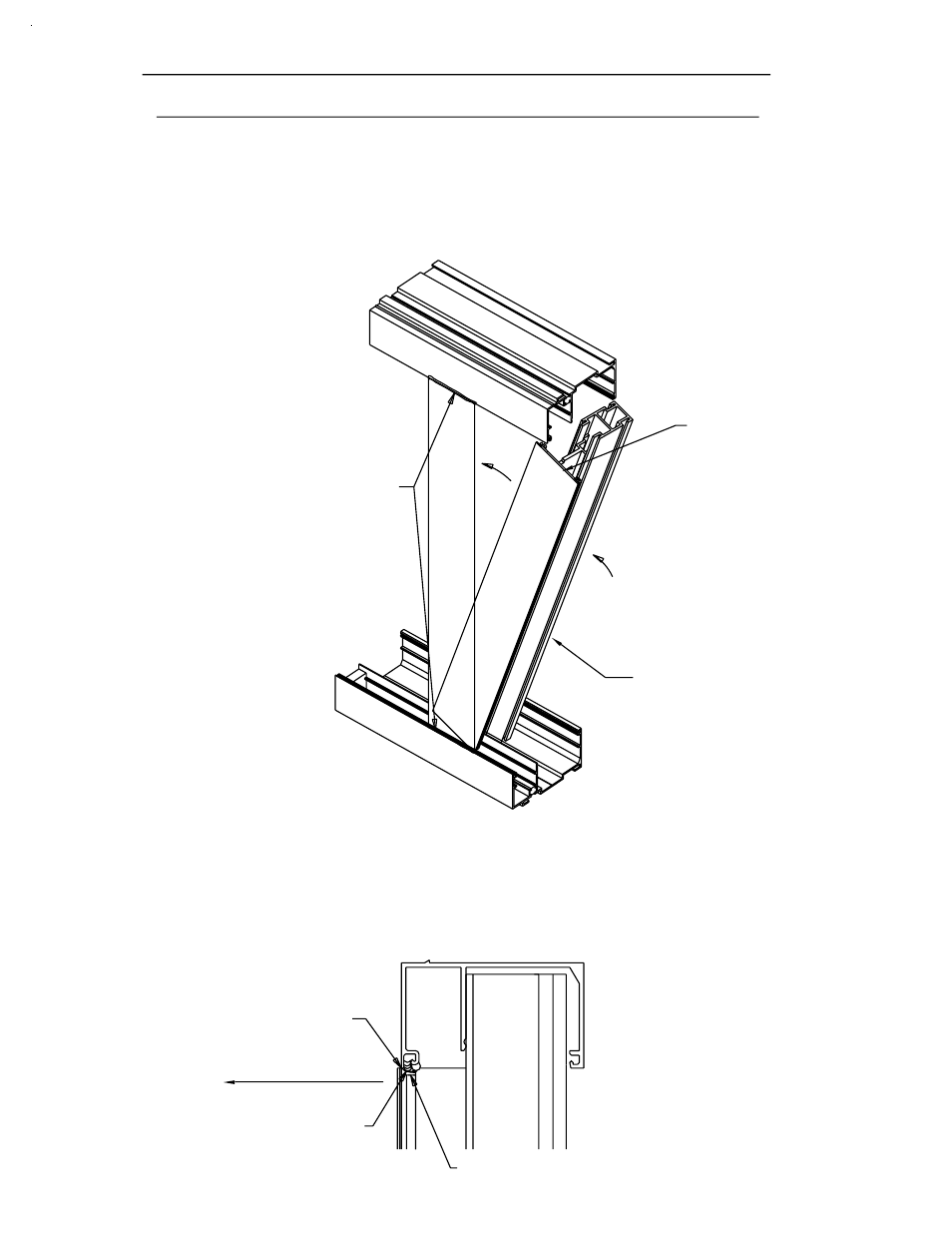
See Fig. 29 below.
THE FINISH ON THE HEAD CAN.
TAKE CARE NOT TO SCRATCH
UNTIL IT IS VERTICAL.
SEALANT IN GASKET
RECEIVER TRACK
HOLD MULLION OUT
NOTCH IN THE VERTICAL
MULLION FACE
[FIG. 29]
DPS 7/2001
Position the vertical mullion assembly angled above the sill can at
the back portion of the head can. The notch in the face portion
of the vertical will allow clearance around the glazing leg at the head.
Swing the captured mullion assembly up, letting the mullion back enter
STEP 4)
[FIG. 28]
the glazing gasket receiver track
Apply a butyl type sealant to
of the vertical mullion location.
at the top and bottom
SWING UP
SECTION IV B - INSTALLATION
vertical set into the back portion of the sill can.
approximately the vertical location. Let the back portion of the
STEP 3)
See Fig. 28 below.
2 pc. JAMB AND INTERMEDIATE VERTICALS
(CONT.)
PAGE 30
NOTE THAT THE
FACE PORTION IS
SHORTER THAN THE
BACK PORTION.
VERTICAL
INTERMEDIATE