Head & sill can splice, Intermediate horizont, Head and sill can splice – EFCO 904 Series User Manual
Page 28: Step 2), Fig. 21, Step 1), Fig. 22
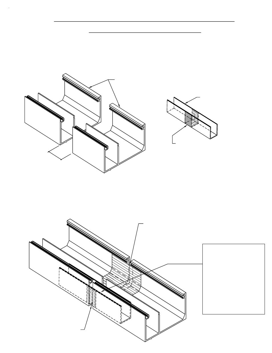
Slide the splice sleeve into the glazing pocket and center the sleeve
over the splice joint. See Fig. 22 below.
HEAD AND SILL CAN SPLICE
The main purpose of this operation is to ensure a water tight
seal between the two lengths of the sill can and prevent water from
entering the interior of the building. See Fig. 21 below.
To ensure proper adhesion of sealant to all parts, clean the sill cans
at the splice area and the splice sleeve with "MEK" to remove all oils.
SPLICE JOINT
CENTERED ON THE
BOND BREAKER TAPE
SPLICE SLEEVE WITH
STEP 2)
JOINT
SPLICE
[FIG. 21]
1/2"
STEP 1)
SECTION IV A - INSTALLATION
SILL CAN
902 - 9484 / K377
904 - 9477 / K379
904 - 8716 / K375
902 - 9845 / K375
904 - 9468 / K379
903 - 9476 / K378
CLV 7/2001
[FIG. 22]
901 - 9479 / K376
AROUND THE SPLICE SLEEVE
BREAKER TAPE WRAPPED
AT THE CENTER AND USED AS
A CAULK BACKER.
WM01 - 1" WIDE BOND
CAN # / SPLICE #
THE SPLICE SLEEVE
AT THE CENTER.
TAPE WRAPPED AROUND
BOND BREAKER
1" WIDE
SPLICE SLEEVE
PAGE 26
902 - 1G66 / K917