Door frame installation, Condensation" brochure, Fig. 56 – EFCO 904 Series User Manual
Page 49: Step 4) step 2) step 3) step 1)
and also in Fig. 57 through Fig. 60 on page 48.
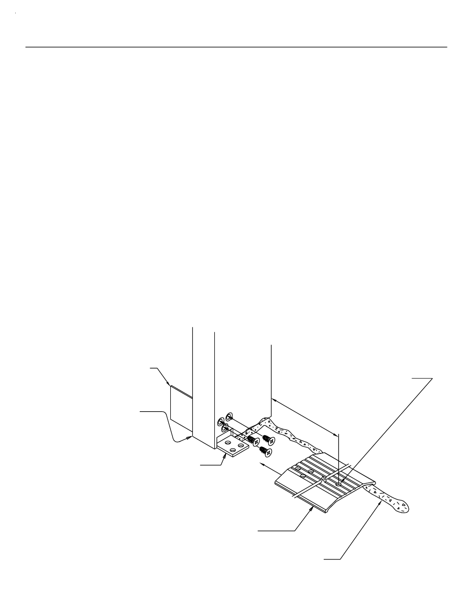
Anchor the door frame and threshold as indicated below in Fig. 56 below
Set the assembled door frame in the opening, plumb and level.
(9950)
THRESHOLD
OF SEALANT
CONTINUOUS BEAD
See the parts description pages in SECTION II for the appropriate
door jamb and transom bar for the system being used.
jamb, continuing under the threshold to the opposite jamb and
connected from the side lite sill can/condition through the door
The concept is to have a continuous bead of sealant at the interior
sealant into the bead of sealant to be applied under the threshold.
to set the member into. Tie the side lite sealant or condition
Apply a bead of sealant around the interior portion of the jamb
SECTION VI A - DOOR FRAME INSTALLATION
Correctly locate the entrance frame in the opening.
NOTE: If an entrance frame is required, it must be installed first.
onto the opposite side lite sill can.
[FIG. 56]
floor and is cut longer
K-153/K-154 Threshold Clip & Screws
@ Concealed Rod Panic
K-124/K-125 Threshold Clip & Screws
than any other vertical
@ Offset Pivots & Butt Hinges
member.
SIDE LITE SILL CAN
The door jamb runs to the
NOTE:
STEP 4)
STEP 2)
STEP 3)
STEP 1)
DPS 7/2001
12" MAX.
THRESHOLD FASTENER
12" FROM JAMB & 12" O.C.
(3) PER SINGLE DOOR
PAGE 47