Head & sill can fabrication, 2) butt gla, E) vertical in – EFCO 904 Series User Manual
Page 15: Fig. 2, Step 3), Step 2), Fig. 1, Step 1), Head and sill can
includes 2 color covers, installed prior to weeping and anchoring.
NOTE: Sill cans with riser legs are bottom weeped and sill cans with flat
903/904
bottoms are face weeped.
HOLE IN BOTTOM
See Fig. 3 on Page 14.
HCW6
[FIG. 2]
HCW6
901/902
HOLE IN FACE
DPS 7/2001
INCLUDES CAPTURED AND BUTT
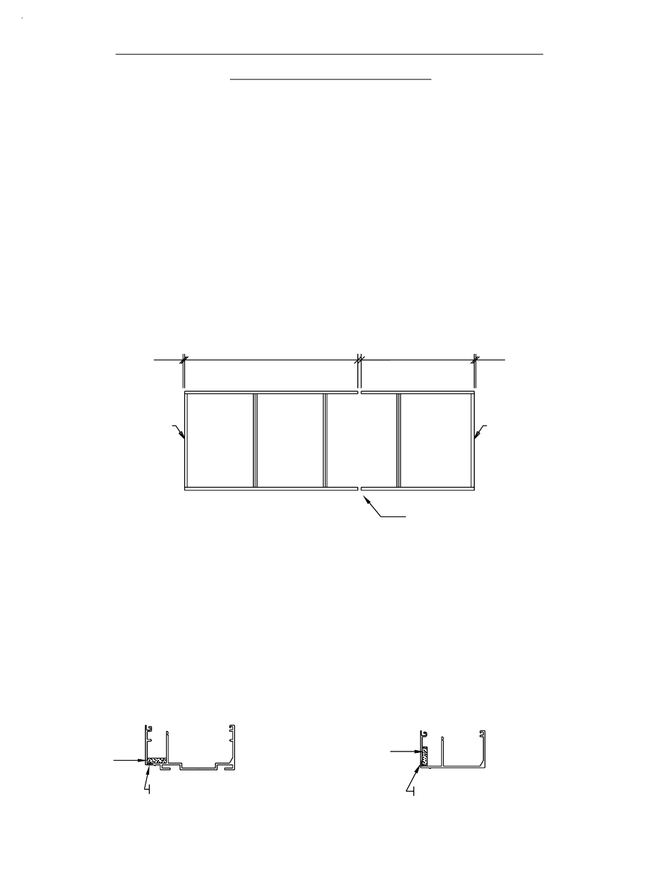
the center of the nearest lite and adjust cut lengths accordingly.
NOTE: Expansion/splice joints are required in elevations that exceed
Measure the opening to determine the cut length of the head
JAMB
"2" color covers that are being used.
and sill frame components. Allow for shims if applicable.
Cut head and sill cans to frame width. This includes any
20 FT. TYPICAL
HEAD & SILL LENGTH
20’-0" in width. Plan for expansion/splice joints to fall at
Drill 1/4" weep holes in sill can 6" from jambs and 48" on
center or if the length is less than 48", drill (1) per lite. This
STEP 3)
JAMB
SHIM
STEP 2)
OPT.
1/4"
[FIG. 1]
EXPANSION/SPLICE
JOINT
SHIM
20 FT. MAXIMUM
1/2"
OPT.
1/4"
SECTION III C - FABRICATION
STEP 1)
GLAZED MULLION SYSTEMS
PAGE 13
HEAD AND SILL CAN