Salter Brecknell 800 Series User Manual
Page 18
CHAPTER 4: SETUP MENU DESCRIPTIONS AND PROCEDURES
4.1
SETUP MENU DESCRIPTIONS
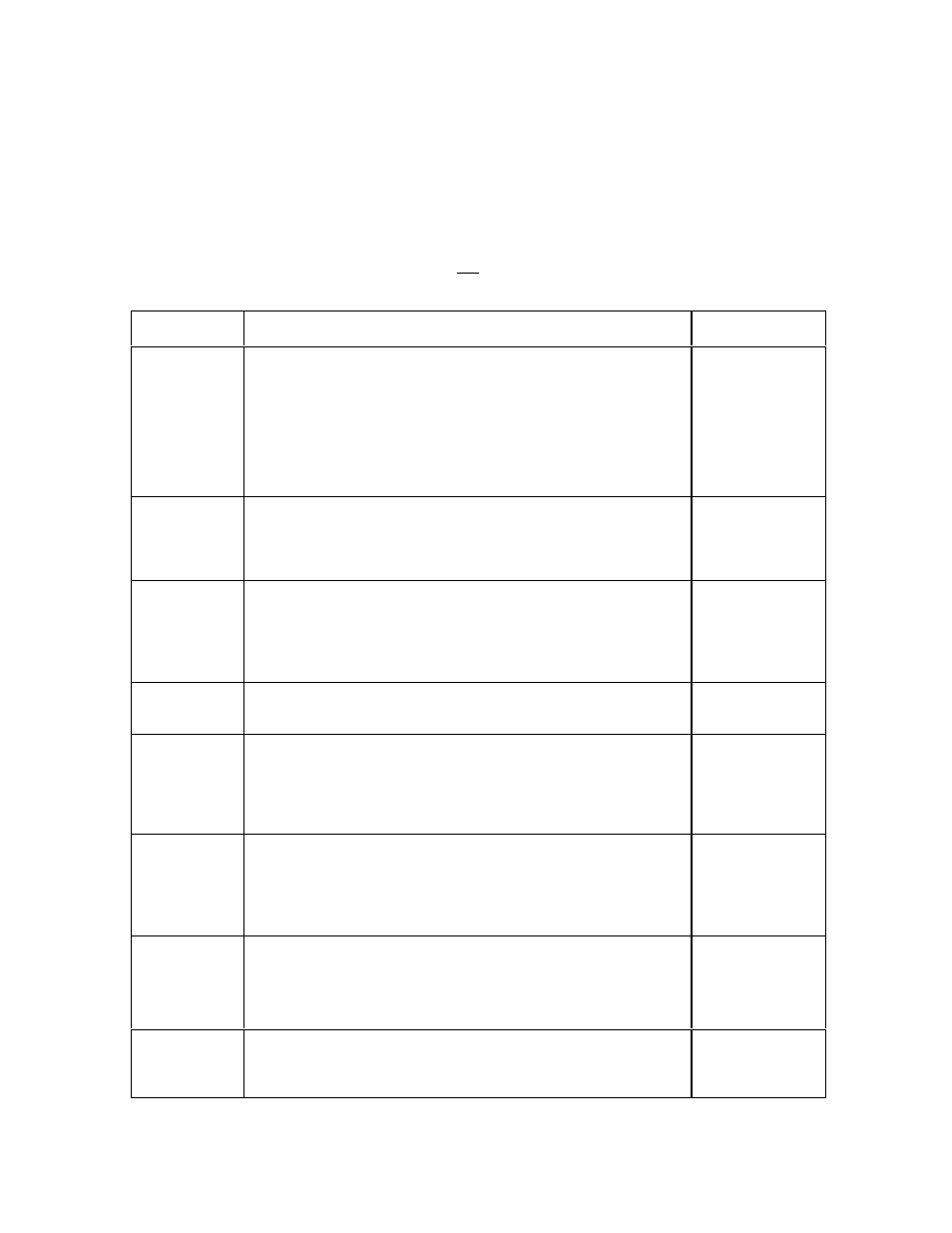
This section provides more detailed descriptions of the selections found in the Setup Menu
Chart. Factory-set defaults are shown in bold with a checkmark (
√
).
Table 4-1 shows the selections that are not allowed for “Legal-for-Trade” applications:
NAME/CODE
DESCRIPTION
CODE/VALUE
F1
Graduations
Specifies number of full-scale graduations. Value should be
consistent with legal requirements and environmental limits on the
useful system resolution.
500 1,000
1,500 2,000
2,500 3,000
4,000 5,000
6,000 8,000
10,000√
√√√
12,000
20,000 30,000
40,000 50,000
F2
Span Gain
Span Gain is related to A/D integration time. The larger the span
gain, the higher the internal resolution, but the slower the update
speed. Note that the scale must be re-calibrated whenever this
parameter is altered. See Appendix C for more information.
25 50
75
100√
√√√
150 200
F3
Zero Track
Band
Selects the range within which the scale will automatically zero. Note
that the scale must be in standstill to automatically zero. Selections
are in Display Divisions.
0d
0.5d√
√√√
1d
3d
5d
F4
Zero Range
Selects the range within which the scale may be zeroed. Note that
the indicator must be in standstill to zero the scale.
100%√
√√√
1.9%
F5
Motion Band
Sets the level at which motion is detected by comparing the present
display update with the previous one. If motion is not detected for two
seconds or more, scale is in standstill and can process a Print or
Zero command. Maximum value varies depending on local
regulations.
1d√
√√√
3d
5d
10d
F6
Digital Filter
Averages weight readings to produce higher stability. The higher the
filter number, the greater the stability but the slower the response
time. Choose 8 or 12 unless a very fast response is needed. Use the
“Auto” setting to automatically determine the filter length as you are
weighing.
Auto√
1 2
4 8
12 16
32 64
F7
Overload Limit
Selects the desired formula which determines the point at which the
indicator shows overload. All selections are based on the primary unit
selected in F8.
"FS" = Full scale in primary units.
FS
FS + 2%√
√√√
FS + 1d
FS + 9d
F8
Calib. Unit
Selects the primary base unit to be used in the calibration process.
Also the default unit for normal operation.
"1" = primary unit is lb. "2" = primary unit is in kg.
1√
√√√
2