And minimum de-active pulse width of t – Cypress Perform CY7C68013 User Manual
Page 52
CY7C68013A, CY7C68014A
CY7C68015A, CY7C68016A
Document #: 38-08032 Rev. *L
Page 52 of 62
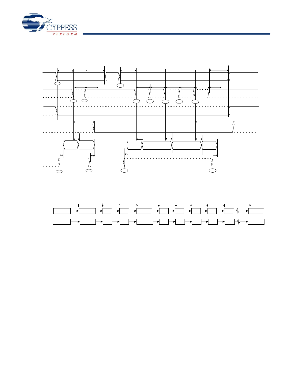
10.17.3 Sequence Diagram of a Single and Burst Asynchronous Read
Figure 32. Slave FIFO Asynchronous Read Sequence and Timing Diagram
Figure 33. Slave FIFO Asynchronous Read Sequence of Events Diagram
shows the timing relationship of the SLAVE FIFO
signals during an asynchronous FIFO read. It shows a single
read followed by a burst read.
■
At t = 0 the FIFO address is stable and the SLCS signal is
asserted.
■
At t = 1, SLOE is asserted. This results in the data bus being
driven. The data that is driven on to the bus is previous data,
it data that was in the FIFO from a prior read cycle.
■
At t = 2, SLRD is asserted. The SLRD must meet the minimum
active pulse of t
RDpwl
and minimum de-active pulse width of
t
RDpwh
. If SLCS is used then, SLCS must be asserted before
SLRD is asserted (The SLCS and SLRD signals must both be
asserted to start a valid read condition.)
■
The data that is driven, after asserting SLRD, is the updated
data from the FIFO. This data is valid after a propagation delay
of t
XFD
from the activating edge of SLRD. In
, data N
is the first valid data read from the FIFO. For data to appear on
the data bus during the read cycle (SLRD is asserted), SLOE
must be in an asserted state. SLRD and SLOE can also be tied
together.
The same sequence of events is also shown for a burst read
marked with T = 0 through 5.
Note In burst read mode, during SLOE is assertion, the data bus
is in a driven state and outputs the previous data. After SLRD is
asserted, the data from the FIFO is driven on the data bus (SLOE
must also be asserted) and then the FIFO pointer is incre-
mented.
SLRD
FLAGS
SLOE
DATA
t
RDpwh
t
RDpwl
t
OEon
t
XFD
t
XFLG
N
Data (X)
t
XFD
N+1
t
XFD
t
OEoff
N+3
N+2
t
OEoff
t
XFLG
t
SFA
t
FAH
FIFOADR
SLCS
Driven
t
XFD
t
OEon
t
RDpwh
t
RDpwl
t
RDpwh
t
RDpwl
t
RDpwh
t
RDpwl
t
FAH
t
SFA
N
t=0
T=0
T=1
T=7
T=2
T=3
T=4
T=5
T=6
t=1
t=2
t=3
t=4
N
N
SLOE
SLRD
FIFO POINTER
N+3
FIFO DATA BUS Not Driven
Driven: X
N
Not Driven
SLOE
N
N+2
N+3
SLRD
N
N+1
SLRD
N+1
SLRD
N+1
N+2
SLRD
N+2
SLRD
N+2
N+1
SLOE
Not Driven
SLOE
N
N+1
N+1