2 connecting a utp segment to the fe-100tx, Connecting a utp segment to the fe-100tx -11, Refer to – Cabletron Systems 2H28-08R User Manual
Page 37: Section 3.5.2
Connecting to the Network
2H28-08R SmartSwitch 2208 User’s Guide
3-11
3.5.2
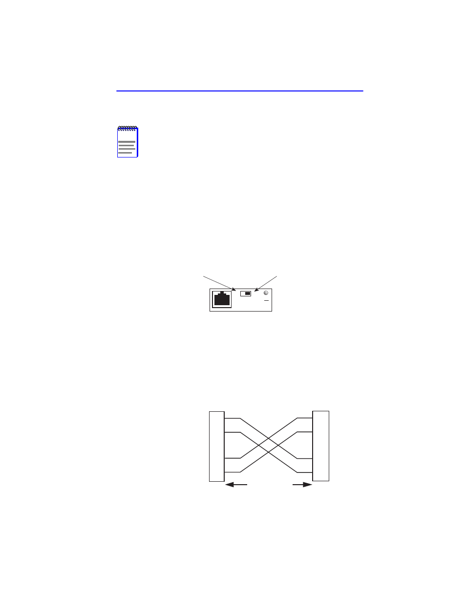
Connecting a UTP Segment to the FE-100TX
An FE-100TX installed in port 7 and/or 8 has an internal crossover
switch. When connecting a workstation, use a straight-through cable and
set the Fast Ethernet Interface Module crossover switch shown in
to the crossed over position marked with X. When connecting
networking devices, such as another bridge, repeater, or router, use a
straight-through cable and set the Fast Ethernet Interface Module
crossover switch shown in
to the straight-through position (not
crossed over), marked with =.
Figure 3-7
FE-100TX Crossover Switch
A schematic of a crossover cable is shown in
. If a cross over is
required, but a crossover cable is not available, use the switch on the
FE-100TX to internally cross over the RJ45 port.
Figure 3-8
Cable Pinouts - RJ45 Crossover Cable
NOTE
To ensure proper operation, use only Category 5 Unshielded
Twisted Pair (UTP) cabling that has an impedance of 85 to
111 ohms.
Position X
(crossed over)
1. RX+
2. RX-
3. TX+
4. NC
5. NC
6. TX-
7. NC
8. NC
Position =
(not crossed over)
1. TX+
2. TX-
3. RX+
4. NC
5. NC
6. RX-
7. NC
8. NC
FE-100TX
10
16651_05
100
=
x
TX+
TX–
RX+
RX–
2
1
3
6
TO
10BASE-T Device Port
TX+
TX–
2
1
3
6
NOTE:
RX+/RX– and TX+/TX–
must share a common
color pair. For example,
the RX+/RX- pair may
use the bw/wb pair, and
the TX+/TX- may use the
ow/wo pair.
TO
RJ45 Port
2251-31
RJ45 to RJ45
RX+
RX–