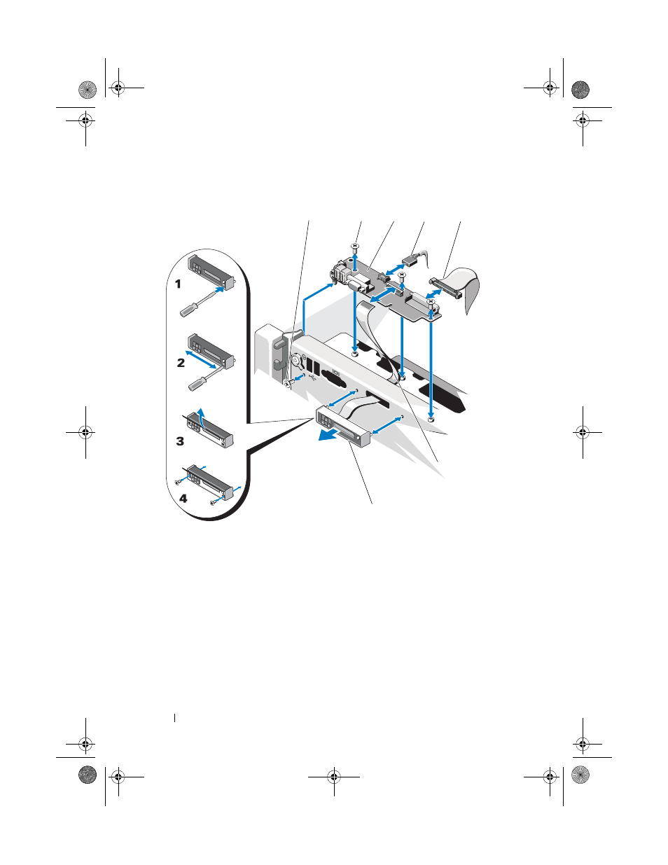
Figure 3-35 – Dell PowerEdge R910 User Manual
Page 164
See also other documents in the category Dell Computers:
- Inspiron 530 (2 pages)
- OptiPlex 755 (82 pages)
- OptiPlex 755 (45 pages)
- OptiPlex 755 (248 pages)
- OptiPlex 755 (622 pages)
- OptiPlex 755 (528 pages)
- OptiPlex 760 (76 pages)
- OptiPlex 760 (203 pages)
- OptiPlex 745 (428 pages)
- OptiPlex 745 (212 pages)
- OptiPlex 745 (360 pages)
- OptiPlex 780 (89 pages)
- OptiPlex 780 (10 pages)
- OptiPlex 780 (74 pages)
- OptiPlex 780 (80 pages)
- OptiPlex 780 (73 pages)
- OptiPlex 780 (40 pages)
- OptiPlex 780 (14 pages)
- OptiPlex GX620 (221 pages)
- OptiPlex GX620 (294 pages)
- OptiPlex GX620 (338 pages)
- Inspiron 530 (226 pages)
- OptiPlex 960 (Late 2008) (16 pages)
- OptiPlex GX260 (100 pages)
- OptiPlex GX260 (235 pages)
- OptiPlex FX160 (Late 2008) (20 pages)
- OptiPlex FX160 (Late 2008) (132 pages)
- OptiPlex FX160 (20 pages)
- OptiPlex 210L (258 pages)
- OptiPlex 210L (150 pages)
- OptiPlex 210L (130 pages)
- OptiPlex 210L (128 pages)
- OptiPlex 210L (300 pages)
- OptiPlex 320 (44 pages)
- OptiPlex 320 (140 pages)
- OptiPlex 320 (132 pages)
- OptiPlex 320 (312 pages)
- OptiPlex 320 (266 pages)
- OptiPlex 320 (356 pages)
- OptiPlex GX240 (86 pages)
- OptiPlex GX240 (283 pages)
- OptiPlex GX240 (298 pages)
- OptiPlex GX240 (182 pages)
- OptiPlex GX240 (144 pages)
- OptiPlex GX240 (121 pages)