Carrier EVERGREEN HFC-134A User Manual
Page 44
44
When connecting the CCN communication bus to a system
element, a color code system for the entire network is recom-
mended to simplify installation and checkout. See Table 14 for
the recommended color codes:
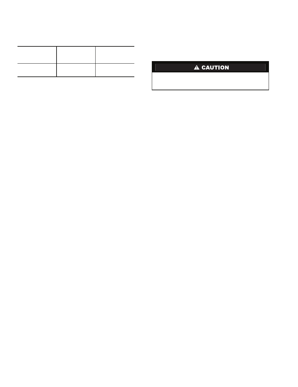
Table 14 — Insulator Codes
If a cable with a different color scheme is selected, a similar
color code should be adopted for the entire network.
NOTE: This color scheme does not apply to SIO wiring
between the CCM and Gateway module.
At each system element, the shields of its communication
bus cables must be tied together. If the communication bus is
entirely within one building, the resulting continuous shield
must be connected to ground at only one single point. See
Fig. 49. If the communication bus cable exits from one build-
ing and enters another, the shields must be connected to ground
at the lightening suppressor in each building where the cable
enters or exits the building (one point only).
To connect the 23XRV chiller to the network, proceed as
follows (see Fig. 49):
1. Route wire through knockout in back of control panel.
2. Strip back leads.
3. Crimp one no. 8 size spring spade terminal on each
conductor.
4. Attach red to “+” terminal and white to “G” terminal and
black to “–” terminal of CCN Network interface located
in the control panel.
Lead-Lag Control Wiring —
The 23XRV can be
wired for lead-lag operation in either series or parallel. See
Fig. 53 for applicable wiring schematics.
Install Field Insulation and Lagging
When installing insulation at the job site, insulate the fol-
lowing components:
• compressor
• discharge pipe assembly
• cooler shell
• cooler tube sheets
• condenser shell
• condenser tubesheets
• suction piping
• economizer
• economizer muffler
• motor cooling drain
• oil reclaim piping
• vaporizer chamber
• refrigerant liquid line to cooler
NOTE: Insulation of the waterbox covers is applied only at the
job site by the contractor. When insulating the covers, make
sure there is access for removal of waterbox covers for servic-
ing (Fig. 54).
SIGNAL TYPE
CCN BUS
CONDUCTOR
INSULATION
COLOR
CCN NETWORK
INTERFACE
(Control Panel)
+
Red
+
Ground
White
G
–
Black
–
Protect insulation from weld heat damage and weld splat-
ter. Cover with wet canvas cover during water piping
installation.