Carrier EVERGREEN HFC-134A User Manual
Page 24
24
5. Remove jacking screws from leveling pads after grout
has hardened.
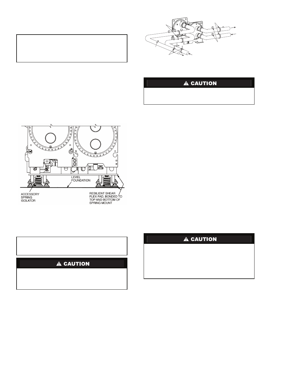
INSTALL SPRING ISOLATION
Spring isolation may be purchased as an accessory from
Carrier for field installation. It may also be field supplied and
installed. Spring isolators may be placed directly under
machine support plates or located under machine soleplates.
See Fig. 34. Consult job data for specific arrangement. Low
profile spring isolation assemblies can be field supplied to keep
the machine at a convenient working height.
Obtain specific details on spring mounting and machine
weight distribution from job data. Also, check job data for
methods to support and isolate pipes that are attached to spring
isolated machines.
Connect Piping
INSTALL WATER PIPING TO HEAT EXCHANGERS —
Refer to Table 4 for nozzle sizes. Install piping using job data,
piping drawings, and procedures outlined below. A typical
piping installation is shown in Fig. 35.
1. Offset pipe flanges to permit removal of waterbox cover
for maintenance and to provide clearance for pipe clean-
ing. No flanges are necessary with marine waterbox
option; however, water piping should not cross in front of
the waterbox cover or access will be blocked.
2. Provide openings in water piping for required pressure
gages and thermometers. For thorough mixing and
temperature stabilization, wells in the leaving water pipe
should extend inside pipe at least 2 in. (51 mm).
3. Install air vents at all high points in piping to remove air
and prevent water hammer.
4. Install pipe hangers where needed. Make sure no weight
or stress is placed on waterbox nozzles or flanges.
5. Water flow direction must be as specified in Fig. 36
and 37.
NOTE: Entering water is always the lower of the 2 noz-
zles. Leaving water is always the upper nozzle for cooler
or condenser.
6. Install waterbox vent and drain piping in accordance with
individual job data. All connections are
3
/
4
-in. FPT.
7. Install waterbox drain plugs in the unused waterbox
drains and vent openings.
8. Install optional pumpout system or pumpout system and
storage tank as shown in Fig. 38-42.
IMPORTANT: Accessory spring isolation packages
are intended solely for non-seismic applications. Seis-
mic applications must be designed by a registered
professional in accordance with all applicable national
and local codes.
IMPORTANT: Chiller water nozzle connections to be
designed by others in accordance with all applicable
national and local codes.
Remove cooler and condenser liquid temperature and
optional pressure sensors before welding connecting piping
to water nozzles. Refer to Fig. 15. Replace sensors after
welding is complete.
Factory-supplied insulation is not flammable but can be
damaged by welding sparks and open flame. Protect insu-
lation with a wet canvas cover.
Never charge liquid 134a refrigerant into the chiller if the
pressure is less than 35 psig (241 kPa). Charge as a gas
only, with the cooler and condenser pumps running, until
35 psig (241 kPa) is reached using a pumpdown. Terminate
the pumpdown mode using the ICVC. Flashing of liquid
refrigerant at low pressures can cause tube freeze-up and
considerable damage.
Fig. 34 — 23XRV Accessory Spring Isolation
(Shown with Accessory Soleplates)
NOTE: The accessory spring isolators are supplied by Carrier for
installation in the field.
a23-1537
PRESSURE
GAGES
PIPE
FLANGES
ENTERING
CONDENSER
WATER
LEAVING
CONDENSER
WATER
AIR VENT
PIPE HANGERS
ENTERING CHILLED
WATER
LEAVING CHILLED
WATER
THERMOMETER
OPENING
(OPTIONAL)
Fig. 35 — Typical Nozzle Piping
a23-1580