Carrier EVERGREEN HFC-134A User Manual
Page 16
16
Lifting the Control Center — Care should be used to prevent
damage due to dropping or jolting when moving the control
center. A fork truck or similar means of lifting and transporting
may be used. Sling in a manner that will equalize the load at the
pickup points. Use a spreader bar if the angle of the sling is less
than 45 degrees relative to horizontal. Do not jolt while lifting.
Use the following procedure to lift the control center.
1. Remove the rubber hole plugs in the top of the control
center and fully thread in 4 eyebolts or swivel hoist rings
(see Fig. 21). Lifting hardware must have
3
/
4
in.-10 x 2 in.
long threads and must have a working load limit of at
least 6000 lb (2722 kg). Typical eyebolts are Chicago
Hardware (size 28) or Grainger (P/N 5ZA63).
2. Attach a sling to the four lifting eyebolts. Make certain
that the angle of the sling is not less than 45 degrees
relative to horizontal.
3. Using an overhead or portable hoist (minimum 2 ton
rated capacity), attach a free-fall chain to the sling
secured to the drive. Take up any slack in the chain.
4. Rig the control center and remove the bolts that secure it
to the VFD mounting brackets on the condenser (see
Fig. 21).
5. Confirm that welding procedures comply with local
Pressure Vessel Codes before removing a portion of the
VFD support bracket from the condenser. Custom brack-
ets should be fabricated if part of the VFD supports must
be cut off of the condenser to reduce the width of the
condenser assembly. Clamp ¼-in. plates over both sides
of the VFD bracket and drill two pairs of holes that
straddle the line along which the VFD brackets will be
cut. This will allow the VFD brackets to be reinstalled
and welded in their original position.
NOTE: To reassemble, follow steps in reverse order. Connect
sensors and cables after major components have been secured
to reduce the risk damaging them. (See Fig. 22.)
REMOVE THE DISCHARGE PIPE ASSEMBLY FROM
THE CONDENSER
NOTE: For steps 1 through 6 refer to Fig. 12.
The condenser relief valve and relief valve vent piping should
be removed if they will interfere with discharge pipe assembly
rigging.
1. Remove the discharge pipe assembly relief valve and
relief valve vent piping.
2. Disconnect the compressor discharge temperature sensor.
3. Disconnect the compressor discharge pressure sensor and
remove the high discharge pressure switch sensor.
4. Rig the discharge pipe assembly and remove the bolts
from the compressor discharge and condenser inlet
flange. Note the position and orientation of the discharge
isolation valve on the condenser inlet flange.
5. Remove the discharge pipe assembly.
6. Cover all openings.
NOTE: To reassemble, follow steps in reverse order. Connect
sensors and cables after major components have been secured
to reduce the risk of damaging them.
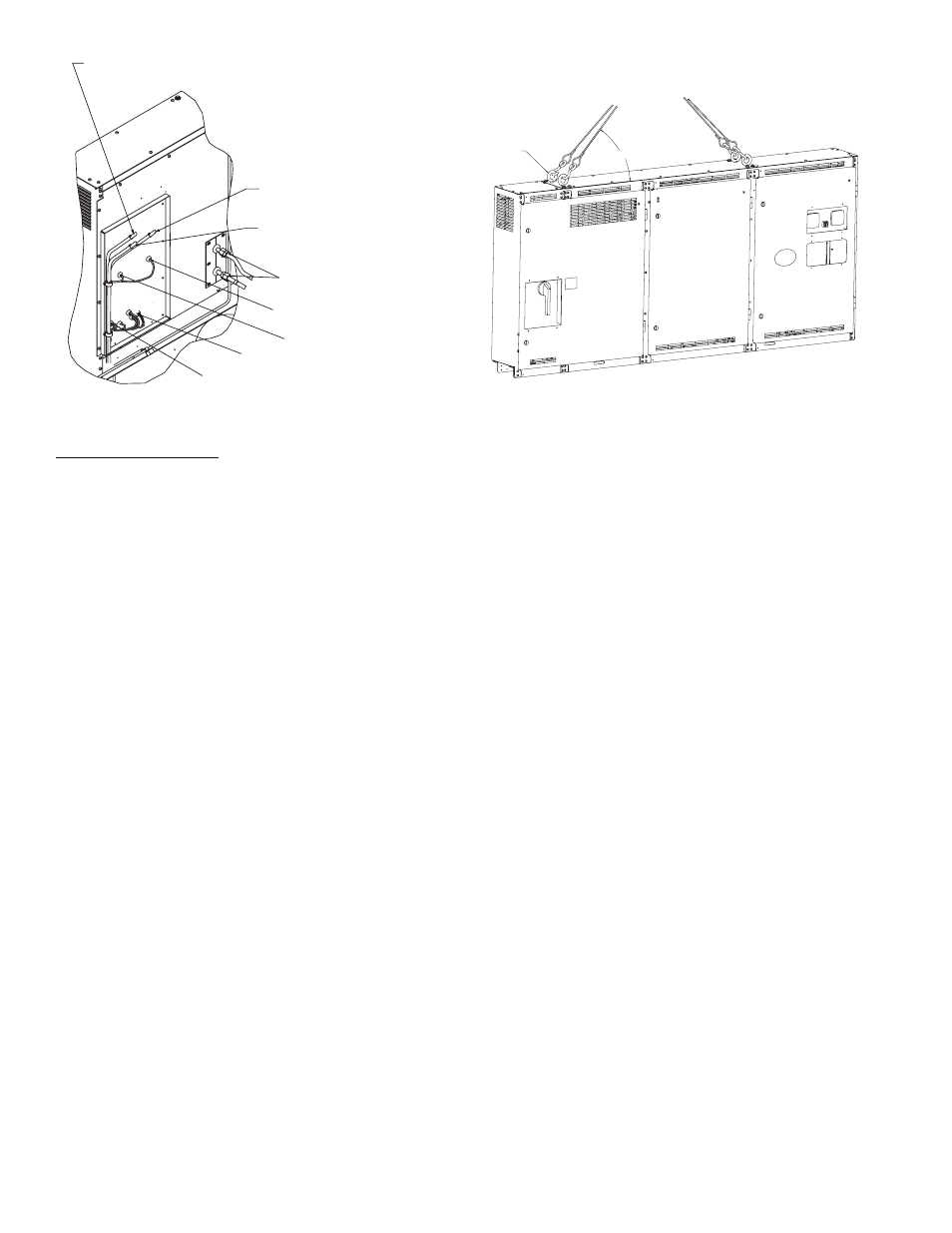
OIL HEATER CONDUIT ASY
OIL PUMP CONDUIT ASY
VAPORIZER HEATER CONDUIT ASY
OIL RECLAIM
ACTUATOR CABLE
VFD COOLING LINE
O-RING FACE SEAL
COUPLINGS
VFD COOLING
SOLENOID CABLE
TEMPERATURE SENSOR
CABLES
PRESSURE SENSOR
CABLES
Fig. 20 — Control Panel Back
a23-1571
45° MIN
LIFTING
EYEBOLT
3/4 IN. - 10 x 2 IN. LIFTING EYEBOLT WITH
SHOULDER OR SWIVEL HOIST RING
6000 LB (2722 KG) WORKING LOAD LIMIT
TYPICAL — CHICAGO HARDWARE P/N 28
GRAINGER P/N 5ZA63
Fig. 21 — Control Center Lifting Points
a23-1561