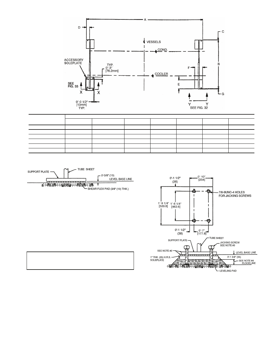
Fig. 31 — 23xrv machine footprint, Fig. 32 — standard isolation, Fig. 33 — accessory isolation – Carrier EVERGREEN HFC-134A User Manual
Page 23: View y-y, View x-x accessory soleplate detail
23
INSTALL ACCESSORY ISOLATION (if required) — Un-
even floors or other considerations may dictate the use of
accessory soleplates (supplied by Carrier for field installation)
and leveling pads. Refer to Fig. 33.
Level machine by using jacking screws in isolation sole-
plates. Use a level at least 24-in. (610 mm) long.
For adequate and long lasting machine support, proper
grout selection and placement is essential. Carrier recommends
that only pre-mixed, epoxy type, non-shrinking grout be used
for machine installation. Follow manufacturer’s instructions in
applying grout.
1. Check machine location prints for required grout
thickness.
2. Carefully wax jacking screws for easy removal from
grout.
3. Grout must extend above the base of the soleplate and
there must be no voids in grout beneath the plates.
4. Allow grout to set and harden, per manufacturer’s
instructions, before starting machine.
IMPORTANT: Chiller support plates must be level
within
1
/
2
in. from one end to the other end of the heat
exchangers for effective oil reclaim system operation.
23XRV
HEAT EXCHANGER
SIZE
DIMENSIONS (ft-in.)
A
B
C
D
E
F
G
30-32
12-10
3
/
4
5-5
1
/
4
0
0-3
5
/
8
1-3
1
/
4
0-9
0-
1
/
2
35-37
14- 7
1
/
4
5-5
1
/
4
0
0-3
5
/
8
1-3
1
/
4
0-9
0-
1
/
2
40-42
12-10
3
/
4
6-0
0-1
1
/
2
0-3
5
/
8
1-3
1
/
4
0-9
0-
1
/
2
45-47
14- 7
1
/
4
6-0
0-1
1
/
2
0-3
5
/
8
1-3
1
/
4
0-9
0-
1
/
2
50-52
12-10
3
/
4
6-5
1
/
2
0-
1
/
2
0-3
5
/
8
1-3
1
/
4
0-9
0-
1
/
2
55-57
14- 7
1
/
4
6-5
1
/
2
0-
1
/
2
0-3
5
/
8
1-3
1
/
4
0-9
0-
1
/
2
Fig. 31 — 23XRV Machine Footprint
a23-1534
VIEW Y-Y
a23-46
NOTES:
1. Dimensions in ( ) are in millimeters.
2. Isolation package includes 4 shear flex pads.
Fig. 32 — Standard Isolation
LEGEND
NOTES:
1. Dimensions in ( ) are in millimeters.
2. Accessory (Carrier supplied, field installed) soleplate package
includes 4 soleplates, 16 jacking screws and leveling pads.
3. Jacking screws to be removed after grout has set.
4. Thickness of grout will vary, depending on the amount neces-
sary to level chiller. Use only pre-mixed non-shrinking grout,
Ceilcote 748 OR Chemrex Embeco 636 Plus Grout 0
′-1½″
(38.1) to 0
′-2¼″ (57) thick.
Fig. 33 — Accessory Isolation
HRS — Hot Rolled Steel
VIEW X-X
ACCESSORY SOLEPLATE DETAIL
a19-1109
a19-1110