Fertilizer relief valve, Fertilizer orifice plates, Fertilizer relief valve fertilizer orifice plates – Great Plains YP4025F-1670 Operator Manual User Manual
Page 68
64
YP4010HD/YP4025/F
Great Plains Manufacturing, Inc.
401-571M
2014-09-08
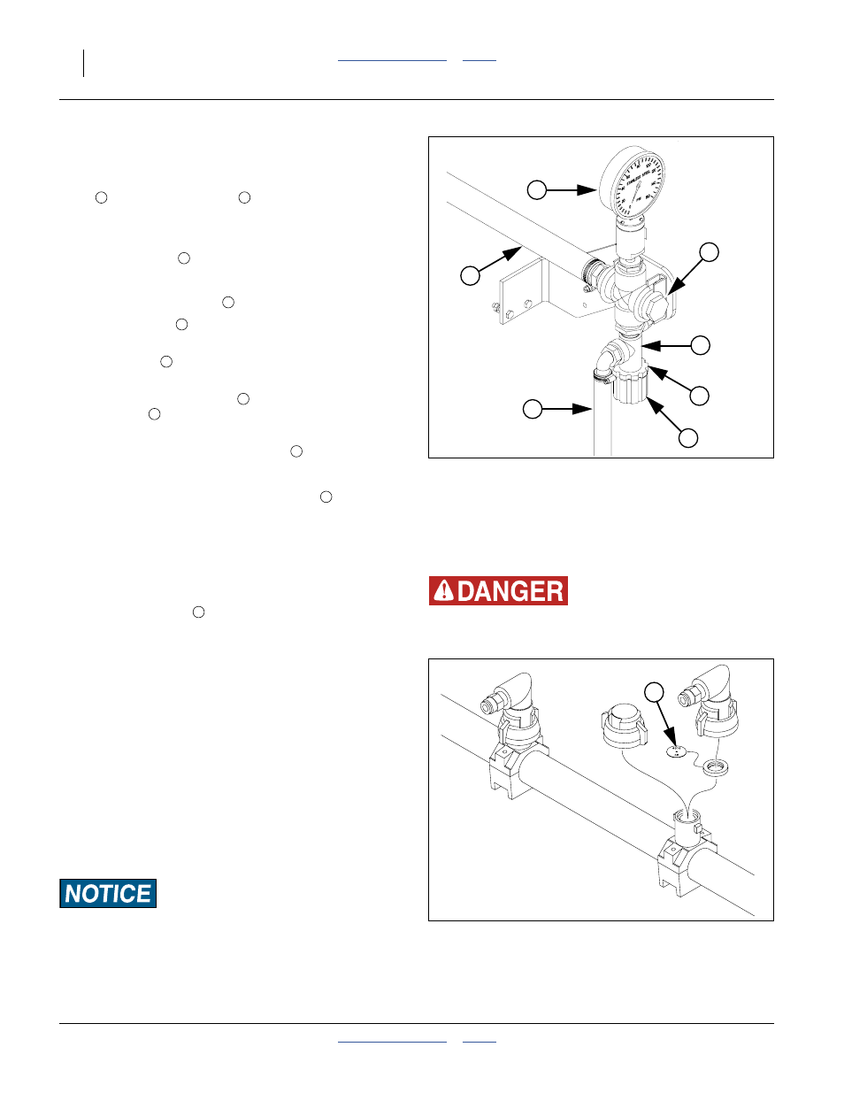
Fertilizer Relief Valve
Refer to Figure 67
When a “Type 2” fertilizer system is installed, a relief
valve
and pressure gauge
are mounted at each
ground drive pump. The relief valve protects the
manifold, lines and fittings from excessive pressure. Any
product that dumps over the relief valve will discharge
from the dump line
in relative safety.
To set relief valve:
1.
Unlock plastic jam nut
from relief valve knob.
2.
Unscrew knob
clockwise (looking down) until it
loses contact with internal spring.
3.
Screw knob
counterclockwise two turns.
Start at this setting.
4.
Observe manifold gauge
and watch for relief valve
dump line
discharge while operating in the field.
5.
If valve is dumping product and gauge reads under
65 psi, stop tractor and turn knob
clockwise
1
⁄
4
turn. Continue operating at normal field speed.
Repeat this step as needed until no product is
discharged from relief valve dump line
.
6.
If the pressure gauge reads above 65 psi, change to
a larger orifice. Go to step 2 and repeat.
Fertilizer Orifice Plates
Refer to Figure 68
In general, the orifice
needs to be small enough to
create at least 15 psi of pressure in the manifold but
large enough to prevent the manifold pressure from
exceeding 65 psi.
The minimum pressure is required to even out the flow of
fertilizer between rows. To reduce orifice plugging and
pump wear, use the largest orifice practical for your
fertilizer application rate. Alternate orifice plates are
listed in the Seed Rate manual.
The best pressure range to maintain is 20-40 psi to
ensure optimum distribution while minimizing leakage.
Built-in check valves at the row units prevent flow below
15 psi.
The Seed Rate Chart book for this planter (manual part
number 401-571B) contains a table of orifice sizes in
gallons per acre.
Orifice plates do not set fertilizer rate.
Rate is set at the pump.
Figure 67
Fertilizer Relief Valve
25164
1
2
3
4
5
6
7
1
2
5
6
7
7
2
5
7
5
Figure 68
Fertilizer Orifice Plate
29984
High Pressure Fluid Hazard:
Wear protective gloves when changing orifice plates.
1
1