520a low speed kit installation – Great Plains YP4025F-1670 Operator Manual User Manual
Page 179
Great Plains Manufacturing, Inc.
Appendix C - Option Installation
175
2014-09-08
401-571M
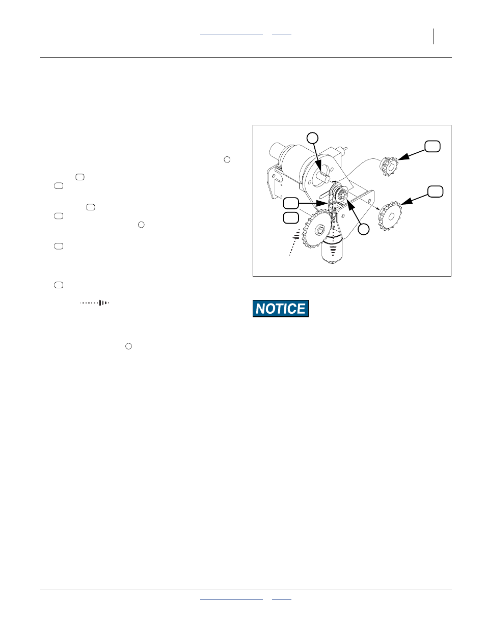
402-520A Low Speed Kit Installation
See “Low Speed Kit” on page 127 for the purpose of
this kit.
1.
Shut off any hydraulic source that powers the
hydraulic seed meter drives (dedicated remotes or
PTO).
Refer to Figure 165
2.
At the hydraulic drive motor, loosen the idler nut
.
Slide the idler out of engagement with the existing
chain
. Remove and save the existing chain:
136-247D CHAIN RL #60 41 PITCHES
3.
Loosen the set screws securing the existing 16T
sprocket
. Remove and save the sprocket:
808-388C SPKT 60B16 X 1 BORE W/KWAY, SS
Leave the woodruff key
in place.
4.
Select one new 10T sprocket:
808-479C SPKT 60B10 X 1 BORE W/KWAY 2SS
Install it on the motor shaft. Secure it with the
woodruff key and two set screws provided.
5.
Select one new:
136-285D CHAIN RL #60 38 PITCHES
Consult page 103 and the directional
arrows
shown on the page for proper chain
clip orientation. Install the new chain on the new
sprocket and existing driven sprocket.
Engage the idler for
1
⁄
4
inch (2.1 cm/m) slack.
Secure the idler nut
.
Field Results Risk:
Do not change the sprocket ratios in the DICKEY-john
®
IntelliAg
®
hydraulic drive setup.
Figure 165
Low Speed Kit Sprocket
36355
16
10
53
1
56
54
57
2
1
53
53
54
54
1
57
56
1