25 series press wheels, Initial setup, Seed monitor console installation – Great Plains YP4025F-1670 Operator Manual User Manual
Page 175
Great Plains Manufacturing, Inc.
Appendix B - Initial and Option Setup
171
2014-09-08
401-571M
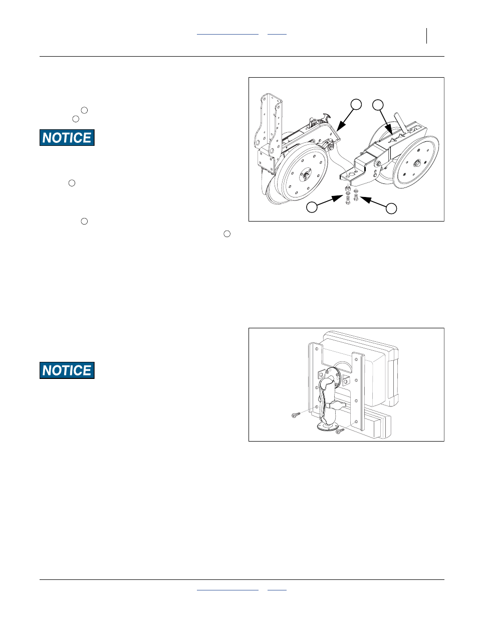
25 Series Press Wheels
Refer to Figure 158
1.
Remove and save the
1
⁄
2
-13x1 in. hex head bolt and
washer
at the back of one of the center row
units
.
There are four bolts at this location. Remove only the hex head
bolts. Do not loosen or remove the square head bolts forward.
2.
Remove and save the
1
⁄
2
-13x1
1
⁄
2
in. hex head
bolt
, washer, and eccentric adjuster nut.
3.
Align the
1
⁄
2
in. holes in the press wheel assembly
with the
1
⁄
2
-13 tapped holes in the row unit, loosely
assemble with the
1
⁄
2
-13x1 in. hex head bolt and
washer
.
4.
Loosely screw in the
1
⁄
2
-13x1
1
⁄
2
in. hex head bolt
,
washer, and eccentric adjuster nut. Rotate the
adjuster to visually align the press wheel assembly
with the row unit, and tight the adjust and both bolts.
Initial Setup
Seed Monitor Console Installation
The planter’s standard seed monitor system includes a
virtual terminal and switch panel that must be mounted in
the tractor cab. As supplied by DICKEY-john
®
, the kit
includes a flat bracket for the modules, and a ball swivel
for mounting the bracket in the tractor.
Mount the modules so that they are easy to monitor during
planting, but do not interfere with safe operation of the tractor
in the field or on public roads.
The ball swivel includes four 10-32 screws. You or your
dealer must provide the mounting holes for the screws.
Your dealer may have alternate suction cup or clamping
brackets available if you prefer to avoid drilling holes.
Refer to the included DICKEY-john
®
manual for harness
connections.
Figure 158
25P Press Wheel Assembly
25383
1
2
4
3
2
3
4
2
4
Figure 159
Terminal and Switch Panel
26303