Appendix b - initial and option setup, Pre-delivery, Install upper marker components – Great Plains YP4025F-1670 Operator Manual User Manual
Page 173: Appendix b - initial and option setup pre-delivery
2014-09-08
401-571M
Great Plains Manufacturing, Inc.
169
Appendix B - Initial and Option Setup
Pre-Delivery
Pre-Delivery items are normally completed by the Great
Plains dealer prior to releasing the implement to the
customer.
Install Upper Marker Components
The marker disks and end tubes are removed for
shipping.
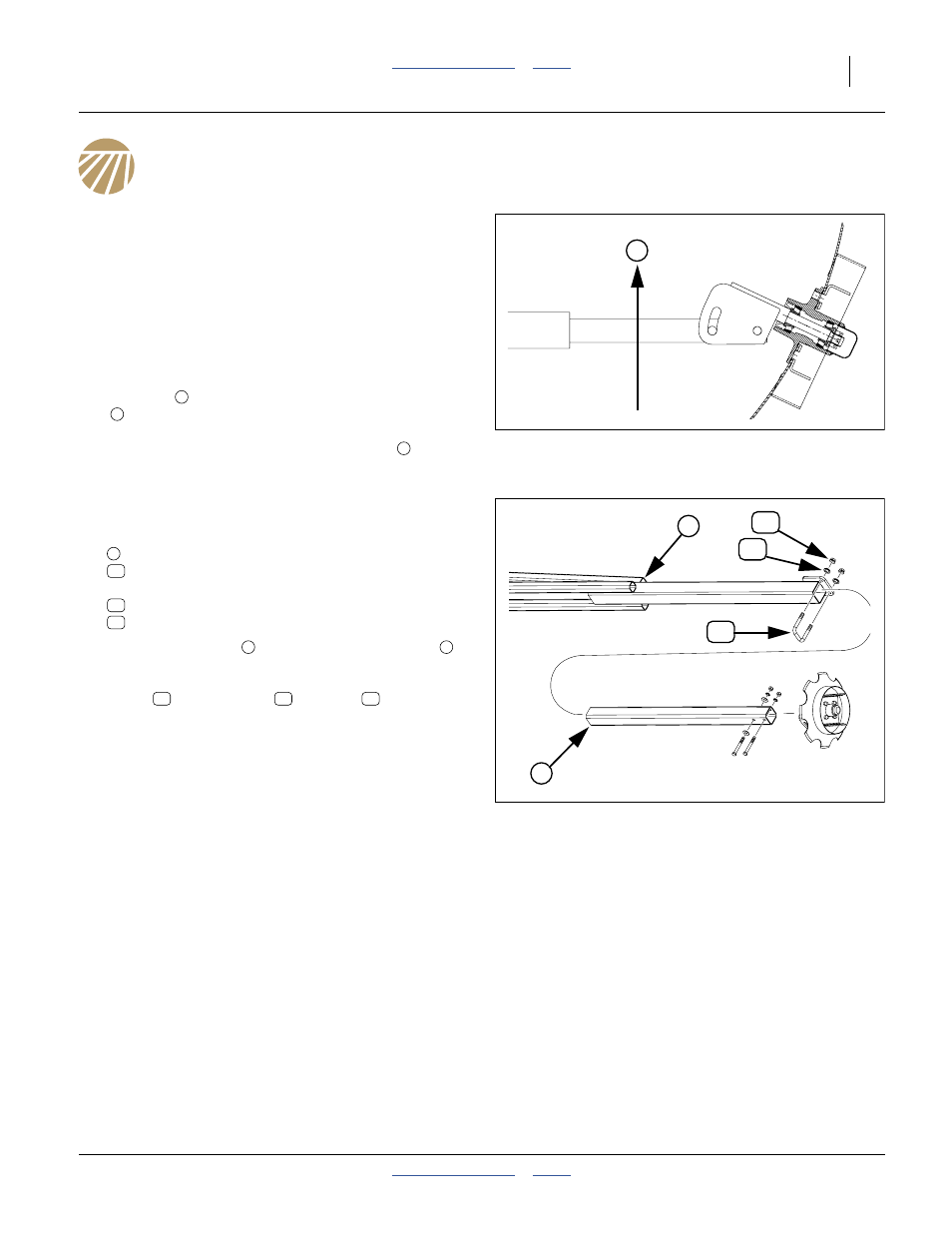
Refer to Figure 154
The end tube
may be inserted into the outer marker
arm
in any of four orientations. Great Plains
recommends that the spindle adjustment allow the disk
to pivot back, away from the direction of travel
.
If the markers are extended for this work, also set the
initial marker extension based on the row spacing.
Refer to Figure 155
1.
At each marker, select one each:
marker disk and tube assembly
806-110C U-BOLT 5/8-11 X 3 1/32 X 4 1/2
and two sets:
803-021C NUT HEX 5/8-11 PLT
804-022C WASHER LOCK SPRING 5/8 PLT
2.
Insert the end tube
into the outer marker arm
.
Insert to initial marker extension value, or about
halfway if extension is not known. Secure with
U-bolt
, lock washers
and nuts
.
Callout, Part & Description cross-references are drawn
from a Reference Page.
Figure 154
Marker Disk Spindle Orientation
11757
T
1
2
T
Figure 155
Marker Final Assembly
29177
51
1
51
50
2
1
51
49
50
1
2
52
51
49