Warning – Great Plains V-300F Operator Manual User Manual
Page 40
V-300, V-300F
148-057M
6/29/2006
38
d.
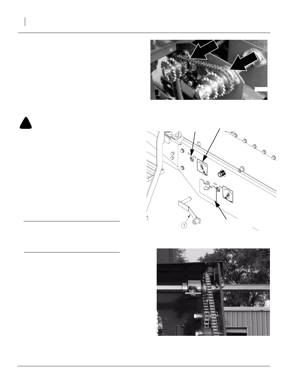
Tighten the idler sprocket on the fertilizer final
drive chain
Move idler sprocket back into place so chain has 6 mm
(1/4-inch) slack.
Refer to Figure 40
4.
To change driver/driven ratio, loosen and slide idler
sprockets out of chain. Remove lynch pins from
shafts. Place correct sprockets on shafts. Store
sprockets not used on ends of shafts. Reinstall chain
and slide idlers back into place so chain has 6 mm
(1/4-inch) slack.
!
WARNING
You may be severely injured or killed by being crushed by the
falling implement. Always have transport locks in place and
frame sufficiently blocked up when working on the implement.
5.
Place a sufficient amount of fertilizer to be calibrated
in the hopper to cover the metering system.
Refer to Figure 41
6.
To calibrate, use the crank handle (1) as a key to
push calibration shaft index collar in and rotate to the
left.
NOTE: Decals located next to calibration shaft index col-
lars indicate proper rotation for calibration and field oper-
ation.
Important! This mechanism controls the direction of
fertilizer flow. By rotating the calibration shaft index
collar to the left using the crank handle (1), the opener
hose is blocked off and fertilizer will collect in the me-
tering tray for calibration.
7.
Remove calibration tray (2) from storage position.
Make sure the calibration tray (2) is in the upright po-
sition, locked in place, and clear of any debris.
Refer to Figure 42
8.
Disengage the seed drive sprocket by pulling the
plunger pin and turning it to be parallel with the drive
shaft.
9.
Raise the drill to the transport position and install
pins in the transport locks. Refer to Transporting,
“Operating Instructions,” page 22.
Dr
iven
Dr
iver
16378
22611
Figure 40
Driver/Driven Sprockets
Figure 41
Calibration Tray and Crank Handle
23268
Figure 42
Seed Drive Sprocket (shown disengaged)
Calibration
Tray
Decal
Calibration
Shaft Index
Collar