Creating an expansion bus network, Installation ~ hardware setup, Device id dip switch settings – ClearOne XAP TH2 User Manual
Page 13
9
Installation
~ Hardware Setup
Technical Services Group ~ 1-800-283-5936 (USA) ~ 1-801-974-3760
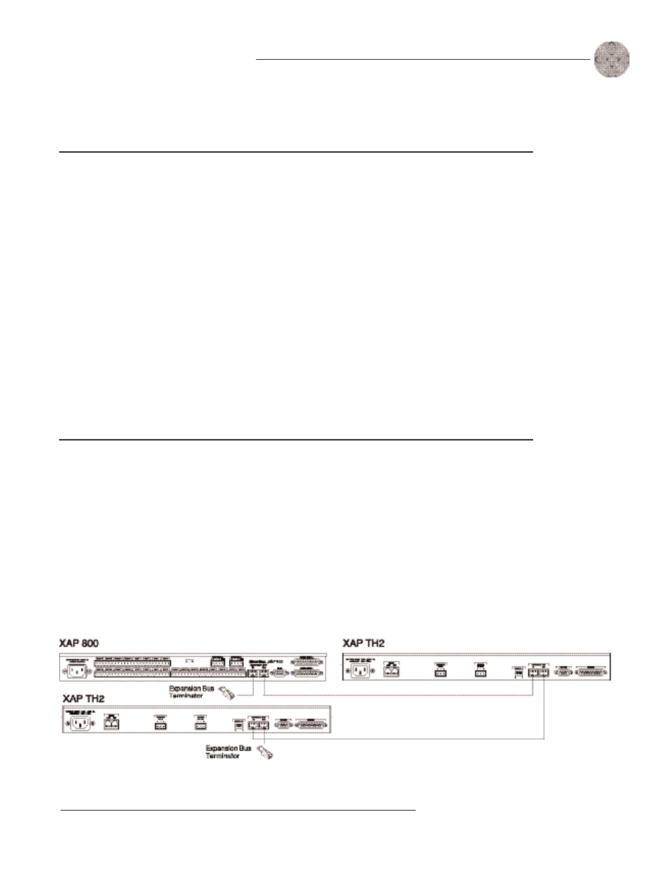
Creating an expansion bus network
1.
Place the XAP TH2 unit in the rack. The back-panel Expansion Bus In and
Expansion Bus Out connectors are designed for setting
up your
expansion bus network. Connections between units are
made in
daisy-chain fashion using category five twisted-pair cable.
2.
The first XAP unit in the chain must have the Expansion Bus In
connector terminated with an Expansion Bus terminator (provided).
Device ID DIP switch settings
Binary
DIP Switch 1
DIP Switch 2
DIP Switch 3
DIP Switch 4
Address
Position
Position
Position
Position
0 (default)
0 (UP)
0 (UP)
0 (UP)
0 (UP)
1
0 (UP)
0 (UP)
0 (UP)
1 ( DOWN)
2
0 (UP)
0 (UP)
1 ( DOWN)
0 (UP)
3
0 (UP)
0 (UP)
1 ( DOWN)
1 ( DOWN)
4
0 (UP)
1 ( DOWN)
0 (UP)
0 (UP)
5
0 (UP)
1 ( DOWN)
0 (UP)
1 ( DOWN)
6
0 (UP)
1 ( DOWN)
1 ( DOWN)
0 (UP)
7
0 (UP)
1 ( DOWN)
1 ( DOWN)
1 ( DOWN)
8
1 (DOWN)
0 (UP)
0 (UP)
0 (UP)
9
1 ( DOWN)
0 (UP)
0 (UP)
1 ( DOWN)
10 (A)
1 (DOWN
0 (UP)
1 ( DOWN)
0 (UP)
11 (B)
1 ( DOWN)
0 (UP)
1 ( DOWN)
1 ( DOWN)
12 (C)
1 ( DOWN)
1 ( DOWN)
0 (UP)
0 (UP)
13 (D)
1 ( DOWN)
1 ( DOWN)
0 (UP)
1 ( DOWN)
14 (E)
1 ( DOWN)
1 ( DOWN)
1 ( DOWN)
0 (UP)
15 (F)
1 ( DOWN)
1 ( DOWN)
1 ( DOWN)
1 (DOWN)
Figure 2.4. E-bus connection diagram