Elr 7000 series multi point lock, Wiring diagrams, 1 timer mode: typical wiring – SARGENT 7000 Series Vertical Rod Lock User Manual
Page 9
1/31/13
Copyright © 2013, Sargen
t Manufacturing Company
, an A
SS
A AB
LO
Y G
roup company
. All right
s reser
ved
.
Reproductions in whole or in par
t without express writ
ten permission of Sargen
t Manufacturing Company is prohibited
.
A8147A • 800-810-WIRE (9473) • www.sargentlock.com
9
ELR 7000 Series Multi Point Lock
Product
8 PIN CONNECTOR
1-Black
2-Red
3-White
4-Green
5-Orange
ACCESS CONTROL DEVICES: ELR 7000 ElectroLynx wire
Color / Function assignments
SARGENT -
ELR 7000
NEG
POS
Timer A
EGND
Timer B
PIN 4 (Green – EARTH GROUND)
PIN 2 (Red – 12 or 24 POS)
PIN 1 (Black – 12 or 24 NEG)
PIN 3 (White – Timer A)
PIN 5 (Orange – Timer B
)
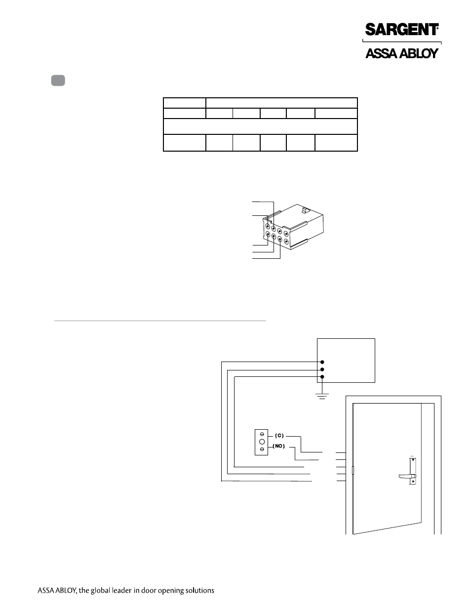
Wiring Diagrams
7
For use when wiring in
TIMER MODE (using the
onboard timer).
If more than 20 seconds timed delay is
necessary, an external timer delay relay is
required (not provided).
Note: 24V supply is constant in
TIMER MODE
.
QC12 Electric Hinge
24VDC
Power Supply
0V (Black)
+24V (Red)
EGND
White
Orange
Green (EGND)
Red (+24V)
Black (0V)
Momentary or
Maintain or Relay Switch (Card
Reader, Access Control, etc.)
( C )
( NO )
Fig. 6 TIMER MODE Typical Wiring
1 Timer Mode: Typical Wiring