Elr 7000 series multi point lock, Mechanical operational check, 2 power mode: typical wiring – SARGENT 7000 Series Vertical Rod Lock User Manual
Page 10
Copyright © 2013, Sargent Manufacturing Company
, an ASSA ABLOY Group company
. All rights reser
ved.
Reproductions in whole or in part without express written permission of Sargent Manufacturing Company is prohibited.
1/31/13
A8147A • 800-810-WIRE (9473) • www.sargentlock.com
10
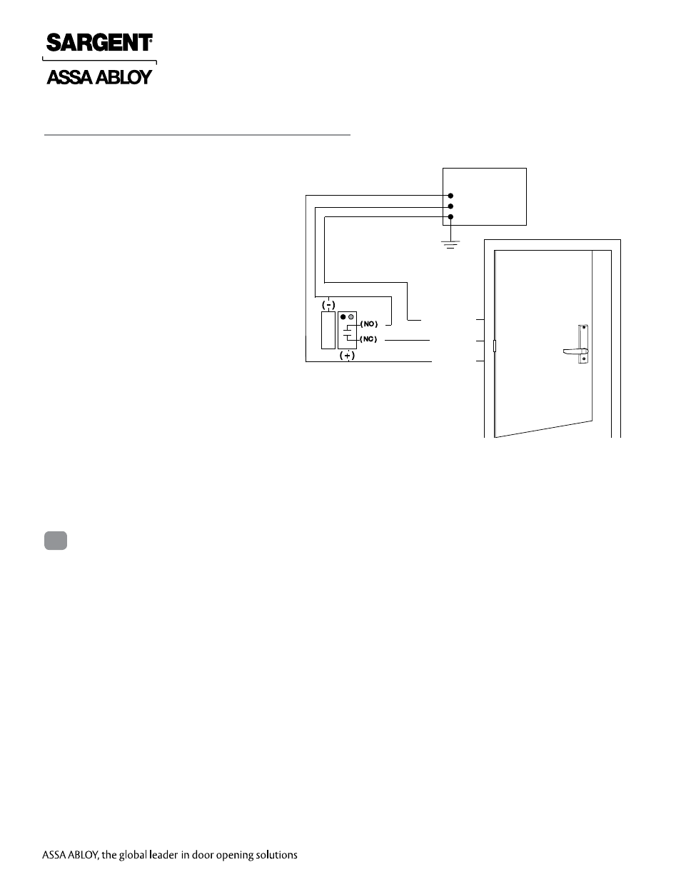
ELR 7000 Series Multi Point Lock
For use when wiring in
POWER MODE.
Notes:
• Onboard timer will not function in
POWER MODE. Add external time delay if
necessary.
• The switch is wired between the power
supply and the load. Do not cycle the
power supply.
24VDC
Power Supply
QC12 Electric Hinge
0V (Black)
+24V (Red)
EGND
Green (EGND)
Red (+24V)
Black (0V)
Maintain
or Relay Switch, i.e., Card
Reader, Access Control, etc.
( + )
( - )
( NO )
( NC )
2 Power Mode: Typical Wiring
For devices without cylinders, go to step 3.
1. For devices with cylinders, insert key into cylinder and rotate.
2. Rotate the lever to retract latch and rods.
8
Mechanical Operational Check
Fig. 2 Power Mode Typical Wiring
- Profile Series v.G1.5 Cylindrical Locks (26 pages)
- Profile Series Mortise Locks (1 page)
- Profile Series Mortise Locks (14 pages)
- Profile Series v.G1.5 Cylindrical Locks (12 pages)
- Profile Series v.G1.5 Cylindrical Locks (2 pages)
- Profile Series v.G1.5 Exit Devices (16 pages)
- Profile Series v.G1.5 Exit Devices (26 pages)
- Profile Series Mortise Locks (1 page)
- Profile Series Mortise Locks (8 pages)
- Profile Series Mortise Locks (2 pages)
- Keypad Cylindrical Locks (26 pages)
- Keypad Mortise Locks (23 pages)
- Keypad Exit Devices (26 pages)
- Profile Series v.G1.5 Mortise Locks (20 pages)
- Profile Series v.G1.5 Mortise Locks (22 pages)
- Profile Series v.G1.5 Mortise Locks (12 pages)
- Profile Series Exit Devices (28 pages)
- Profile Series v.G1.5 Cylindrical Locks (18 pages)
- Profile Series v.G1.5 Cylindrical Locks (12 pages)
- Passport 1000 PG Exit Devices (28 pages)
- Passport 1000 PG Mortise Locks (22 pages)
- Passport 1000 PG Cylindrical Locks (22 pages)
- Passport 1000 P2 Mortise Lock (1 page)
- Profile Series v.S2 Mortise Locks (2 pages)
- Profile Series v.S2 Mortise Locks (2 pages)
- IN100 Mortise Locks (20 pages)
- 11 Line Lever Lock (1 page)
- 11 Line Lever Lock (4 pages)
- 10 Line Cylindrical Lock (2 pages)
- 10 Line Cylindrical Lock (1 page)
- 7 Line (4 pages)
- 10 Line Cylindrical Lock (1 page)
- 10 Line Cylindrical Lock (2 pages)
- 10 Line Cylindrical Lock (4 pages)
- DL Series Tubular Lock (3 pages)
- RDL Tubular Lock with Simpli Roseless Trim (2 pages)
- 6500 Line (2 pages)
- GX Series (3 Line) (2 pages)
- GX Series (3 Line) (4 pages)
- 9898 Reversible Rim (2 pages)
- 8200 Ecoflex Electrified Mortise Lock (8 pages)
- 9200 High Security Locksets (1 page)
- 50- Prefix/185S Kit Secured Indicator Rose (2 pages)
- 3P8225 Levers (4 pages)
- 8200 Lever Lock (4 pages)