Power mode installation instructions – SARGENT 7000 Series Vertical Rod Lock User Manual
Page 11
1/31/13
Copyright © 2013, Sargen
t Manufacturing Company
, an A
SS
A AB
LO
Y G
roup company
. All right
s reser
ved
.
Reproductions in whole or in par
t without express writ
ten permission of Sargen
t Manufacturing Company is prohibited
.
A8147A • 800-810-WIRE (9473) • www.sargentlock.com
11
ELR 7000 Series Multi Point Lock
Electrical Operational Check
9
1. POWER MODE Installation Instructions
How it works: The ELR module retracts when power is applied and
releases when power is removed.
1. Mount ELR 7000 Multi-point device using instruction sheet(s)
provided.
Note: Ensure proper mechanical function before attempting
electrical retraction:
• Verify the levers can be full rotated and the latch is fully
retracted.
• Adjust device mechanically, as required, before applying
power.
SECTION I: POWER MODE
In this configuration, the device is not energized when locked. When energized with a 12 or 24 volt input,
the latch(es) will retract and remain in the retracted position until power is removed. Power is typically ap-
plied through a relay triggered by an access control device.
For installations using the onboard timer circuit, refer to SECTION II:
TIMER MODE.
5. Apply 12V or 24V according to ELR input requirements (below):
Confirm that the LED is blinking, that the system fully unlocks, and that
all bolts clear the strikes. Troubleshoot the device if issues are observed
using the steps outlined at the end of the POWER MODE section.
6. Store excess wiring under cover and assemble
with provided screws. Avoid pinching wires.
2. Connect the ElectroLynx harness in the door
(Fig. 2 POWER MODE Installation):
Plug the 8-pin ElectroLynx connector from the rail into the ElectroLynx harness or splice into
non-ElectroLynx harness.
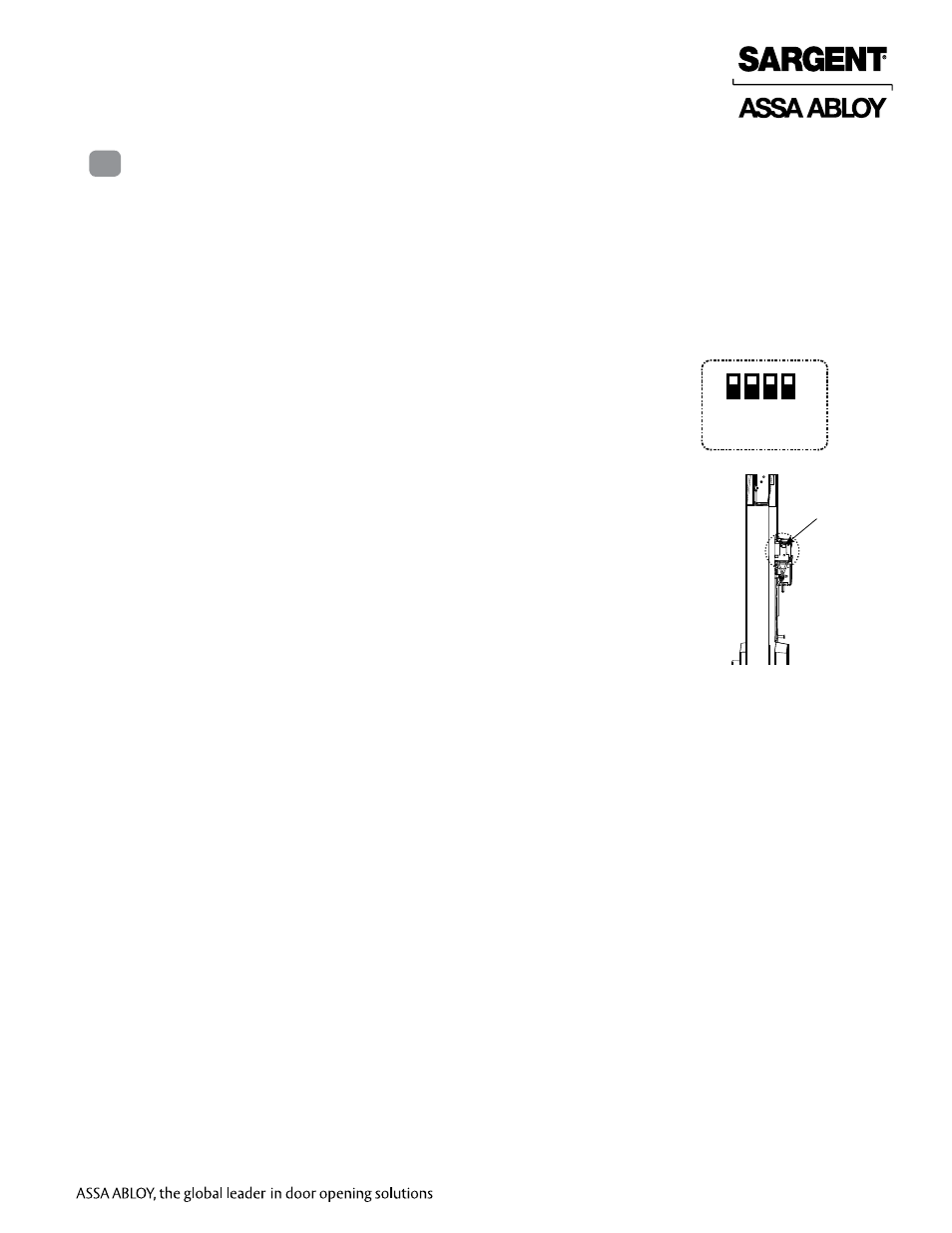
3. Ensure all four DIP switches are in the UP position. This enables power mode.
4. Connect the ElectroLynx harness to the hinge and secure the electric hinge to door.
Notes: Make sure no wires are pinched or damaged in the process. Refer to detailed wiring
instructions under POWER MODE wiring.
Fig. 1 Power Mode Settings
1 2 3 4
UP
Fig. 2 Settings Location
DIP switch
setting location