Elr 7000 series multi point lock, Timer mode installation instructions – SARGENT 7000 Series Vertical Rod Lock User Manual
Page 14
Copyright © 2013, Sargent Manufacturing Company
, an ASSA ABLOY Group company
. All rights reser
ved.
Reproductions in whole or in part without express written permission of Sargent Manufacturing Company is prohibited.
1/31/13
A8147A • 800-810-WIRE (9473) • www.sargentlock.com
14
ELR 7000 Series Multi Point Lock
SECTION II: TIMER MODE
In this configuration, the device is always energized with a 24 or 12 volt input, and a timer circuit is opened or closed
to control rod retraction. A
momentary or maintain switch is typically used to perform this operation.
For installations where the power input is cycled to retract the device, refer to SECTION I:
POWER MODE.
When TIMER MODE is used in conjunction with an external device, such as a door operator, a keypad/reader with
two relays are required. Otherwise, an external relay board is required.
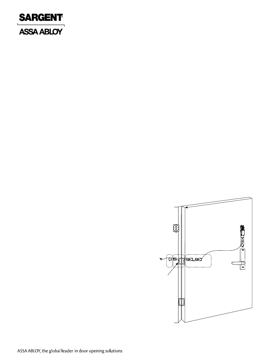
1. TIMER MODE Installation Instructions
How it works: ELR module retracts when timer input circuit is closed.
1. Mount ELR 7000 Multi-point device using installation instruction sheet(s) provided.
Note: Ensure proper mechanical function before attempting electrical retraction:
• Verify the levers can be fully rotated and the latch is fully retracted.
• Adjust device mechanically, as required, before applying power.
Stand Alone ELR
McKinney QC8 Electric Hinge
(with 8-pin connectors)
Fig. 1 TIMER MODE Installation
ELR Input Requirements
Voltage: 24VDC
• Filtered and regulated power supply
• Motor operating current: 700mA
• Motor hold current: 150mA
Note: Earth Ground is required for Electrostatic Dis-
charge (ESD) protection unless the metal door and
frame are already earth grounded; otherwise, earth
ground wiring is required at pin 4 (Fig. 2 ElectroLynx
TIMER MODE Wiring).
2. Ensure DIP Switch switch (position 1) disables POWER MODE. Set to DOWN to disable.
3. Connect the ElectroLynx harness in the door (Fig. 2 ElectroLynx TIMER MODE Wiring):
Plug the 8-pin ElectroLynx connectors from the device into the ElectroLynx harness or splice
into a non-ElectroLynx harness (Fig. 1 TIMER MODE Installation).
Voltage: 12VDC
• Filtered and regulated power supply
• Motor operating current: 850mA
• Motor hold current: 250mA