Elr 7000 series multi point lock, 3 install outside trim and inside trim, 4 inside mounting plate & elr assembly – SARGENT 7000 Series Vertical Rod Lock User Manual
Page 7: A. outside trim
1/31/13
Copyright © 2013, Sargen
t Manufacturing Company
, an A
SS
A AB
LO
Y G
roup company
. All right
s reser
ved
.
Reproductions in whole or in par
t without express writ
ten permission of Sargen
t Manufacturing Company is prohibited
.
A8147A • 800-810-WIRE (9473) • www.sargentlock.com
7
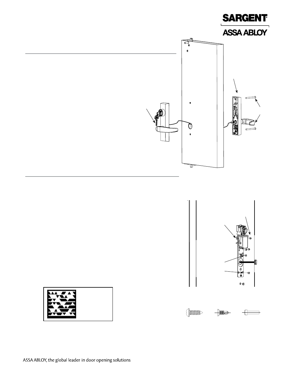
ELR 7000 Series Multi Point Lock
1. Mount inside trim lever to outside trim lever using
(2) # 1/4” -20 x 3” Phillips oval head machine screws.
Fig. 3
Inside trim
Outside trim
A. Outside Trim
3 Install Outside Trim and Inside Trim
1. Install the upper left mounting screw, #8 - 32 x 5/8 Fillister head
for metal door & #8 x 5/8 self tapping Fillister for wood doors.
See Figure 4A.
Note: Leave the screw loose enough to slide the ELR assembly
on.
2. Snake the wire through the ELR assembly.
3. Slide the mounting clip of the ELR Assembly underneath the
installed screw and secure in place.
4. Tighten the upper left mounting screw.
Note: Be careful not to pinch or disconnect the wire located
in that area.
5. Install the remaining (3) 8-32 x 5/8 Fillister mounting screws on
metal doors.
6. Install the remaining #8 x 5/8 self tapping Fillister mounting screws
(wood doors).
7. Install (2) 1/2” self-tapping screws on either diagonal, Figure 4B,
one above molex connector and one below.
8. Connect the 8-pin molex connectors.
4 Inside Mounting Plate & ELR Assembly
#8-32 x 5/8”
Fig. 4
(2) 1/4”
self-tapping
screws
Scan to see a
video of this
installation step.
Fig. 4A
Fig. 4B
Fig. 4C
#8-32 x 5/8”
#8-32 x 5/8”