Elr 7000 series multi point lock, General description, Hardware specifications – SARGENT 7000 Series Vertical Rod Lock User Manual
Page 3: Electronic specifications, Wire gauge charts, 7000 series multi point lock
1/31/13
Copyright © 2013, Sargen
t Manufacturing Company
, an A
SS
A AB
LO
Y G
roup company
. All right
s reser
ved
.
Reproductions in whole or in par
t without express writ
ten permission of Sargen
t Manufacturing Company is prohibited
.
A8147A • 800-810-WIRE (9473) • www.sargentlock.com
3
ELR 7000 Series Multi Point Lock
The SARGENT stand alone ELR 7000 series multi point lock is designed to automatically retract the
rods, concealed within the door.
• Certified ANSI/BHMA A156.3 Grade 1
• Fire rated devices available
• UL and CUL listed for use on Fire Doors
• Multi point lock furnished for 1-3/4” doors
• Wire from EAC Panel to door must be shielded
with a drain terminated at EAC Panel controller
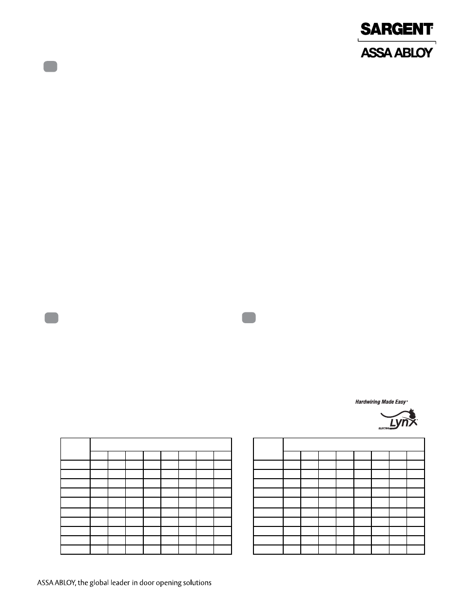
Wire Gauge Charts
Total
One-Way
Length of
Wire Run (ft)
Load Current @ 12VDC
1/4A
1/2A
3/4A
1A
1-1/4A
1-1/2A
2A
3A
100
20
18
16
14
14
12
12
10
150
18
16
14
12
12
12
10
—
200
16
14
12
12
10
10
—
—
250
16
14
12
10
10
10
—
—
300
16
12
12
10
10
—
—
—
400
14
12
10
—
—
—
—
—
500
14
10
10
—
—
—
—
—
750
12
10
—
—
—
—
—
—
1,000
10
—
—
—
—
—
—
—
1,500
10
—
—
—
—
—
—
—
Total
One-Way
Length of
Wire Run (ft)
Load Current @ 24VDC
1/4A
1/2A
3/4A
1A
1-1/4A
1-1/2A
2A
3A
100
24
20
18
18
16
16
14
12
150
22
18
16
16
14
14
12
10
200
20
18
16
14
14
12
12
10
250
18
16
14
14
12
12
12
10
300
18
16
14
12
12
12
10
—
400
18
14
12
12
10
10
—
—
500
16
14
12
10
10
—
—
—
750
14
12
10
10
—
—
—
—
1,000
14
10
10
—
—
—
—
—
1,500
12
10
—
—
—
—
—
—
7000 Series Multi Point Lock
• Cylinder override available for 7000 CVR with
106 Series Auxiliary Control
12VDC System
• 12VDC ELR Draw = 850mA
24VDC System
• 24VDC ELR Draw = 700mA
General Description
2
Hardware Specifications
3
Electronic Specifications
4
1. Functions
The 7000 ELR can be configured to work in either of two modes:
POWER MODE (see Section II: POWER MODE)
The device is not energized when locked. When electrified, the device and remain in the retracted posi-
tion until power is removed. Power is typically applied through a relay triggered by an access control
device.
TIMER MODE (see Section III: TIMER MODE)
The device is always energized and retraction is triggered by a momentary or maintain switch.
In TIMER MODE:
When the timer circuit is closed using a momentary switch, the device retracts, remains retracted for a set
duration, and releases. The duration of the retraction is set through an onboard timer setting.
When the timer circuit is closed using a maintain switch, the device retracts. The device releases when
the contact is opened.
2. Important
Caution: Disconnect all input power before servicing.
Installer must be a trained and experienced service person.
Wiring must comply with applicable local electrical codes, ordinances and regulations.
3. Installation Notes
Earth Ground: Required for electrostatic discharge (ESD) protection, unless already grounded through
the metal door and frame.