Transmig 175i – Tweco 175i Transtig User Manual
Page 35
TRANSMIG 175i
Manual 0-5143
3-17
INSTALLATION, OPERATION AND SETUP
A-09586_AC
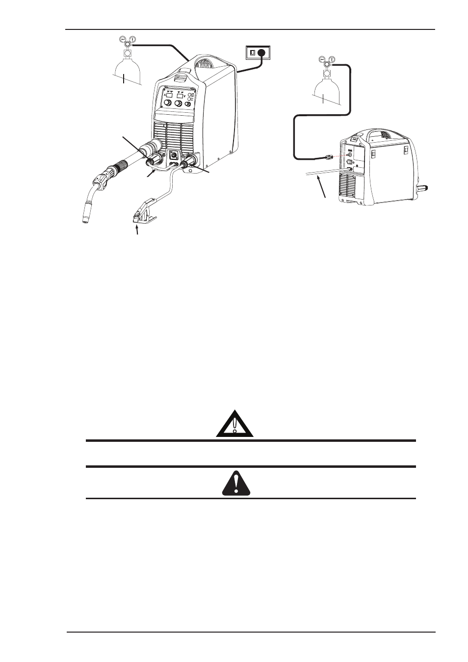
Shielding Gas Hose Fitted
with Quick
Connect
Supply Input Lead
Work Lead
Negative Welding
Terminal (-)
Positive Welding
Terminal (+)
MIG Torch
Polarity Lead
MIG Torch
Figure 3-15: Setup for Mig Welding with Gas Shielded Mig Wire
3.16 Setup for MIG (GMAW) Welding with Gasless Mig Wire
A. Select MIG mode with the process selection control (refer to Section 3.06.13 for further information).
B. Connect the Mig Torch polarity lead to the negative welding terminal (-). If in doubt, consult the electrode
wire manufacturer. Welding current flows from the power source via heavy duty bayonet type terminals.
It is essential, however, that the male plug is inserted and turned securely to achieve a sound electrical
connection.
C. Connect the work lead to the positive welding terminal (+). If in doubt, consult the electrode wire manufacturer.
Welding current flows from the power source via heavy duty bayonet type terminals. It is essential, however,
that the male plug is inserted and turned securely to achieve a sound electrical connection.
D. Refer to the Weld Guide located on the inside of the wirefeed compartment door for further information.
!
WARNING
Before connecting the work clamp to the work make sure the mains power supply is switched
off.
CAUTION
Loose welding terminal connections can cause overheating and result in the male plug being fused
in the terminal.
Remove any packaging material prior to use. Do not block the air vents at the front or rear of the
Welding Power Source.