Section 4: operation, 01 power supply control panel, 02 system operation – Tweco 100 Ultra-Cut Plasma Cutting System with Automated Gas Control User Manual
Page 71: Section 4: operation -1, Power supply control panel -1, System operation -1, Ultra-cut 100 xt
ULTRA-CUT 100 XT
Manual 0-5303
OPERATION
�-1
SECTION 4: OPERATION
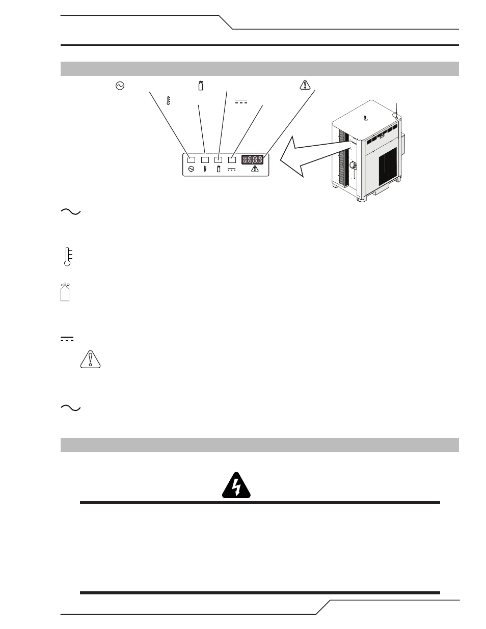
4.01 Power Supply Control Panel
Art # A-11541_AB
AC Indicator
Temp Indicator
Gas Indicator
DC Indicator
A/
Status Indicator
A/
AC Power Lamp
Indicates unit has passed the input power tests and AC power is being supplied to the inverter modules via the
input contactor when the ON/OFF switch is in ON position.
TEMP Lamp: Normally OFF. Lamp will come ON when the internal temperature sensors detect temperatures
above normal limits. Let the unit cool before continuing operation.
GAS Lamp: Flashing during start up gas purge/pump priming, then steady whenever gas is flowing. Indicates
adequate gas pressure and coolant flow for operation.
DC Lamp: Indicates the power supply is generating output DC voltage.
A/
Status Indicator: Shows CCM code version on start up followed by the Current Control setting and
system status. Refer to Section 4.05 and Status Code Section for details.
Rear Panel AC Power Lamp
Indicates AC power is present inside the unit
4.02 System Operation
This section contains operating information which is specific to the power supply.
WARNINGS
Review the safety precautions in Section 1.
If the power supply cord has a plug or is not permanently connected to power, be sure the power to the
outlet is disconnected when inserting the plug into the outlet.
Disconnect primary power at the source before assembling or disassembling power supply, torch parts,
or torch and leads assemblies, or adding coolant.
It is not enough to simply move the ON/OFF switch on the unit to OFF position when cutting operations have
been completed. Always open the power supply disconnect switch five minutes after the last cut is made.