18 dmc-3000 gas manifold control installation – Tweco 400 Ultra-Cut XT Plasma Cutting System User Manual
Page 52
ULTRA-CUT 100 XT/200 XT/300 XT/400 XT
3-24
INSTALLATION
Manual 0-5297
3.18 DMC-3000 Gas Manifold Control Installation
The DMC-3000 Gas Control must be installed in a suitable location where it is easily accessible to the system op-
erator. The unit must be mounted to a flat horizontal surface. If the Module is mounted to any support subject to
vibration or motion, the installer must fasten the module to the support securely.
The Module should be located as far away as possible from the Arc Starter due to possible electromagnetic interfer-
ence. It is acceptable to locate the control cable in the same track as the cables from the Arc Starter and away from
torch leads.
The Module includes feet which lift the bottom panel of the mounting surface. Louvers on the back panel of the
module must remain unblocked, for the free passage of ventilating air.
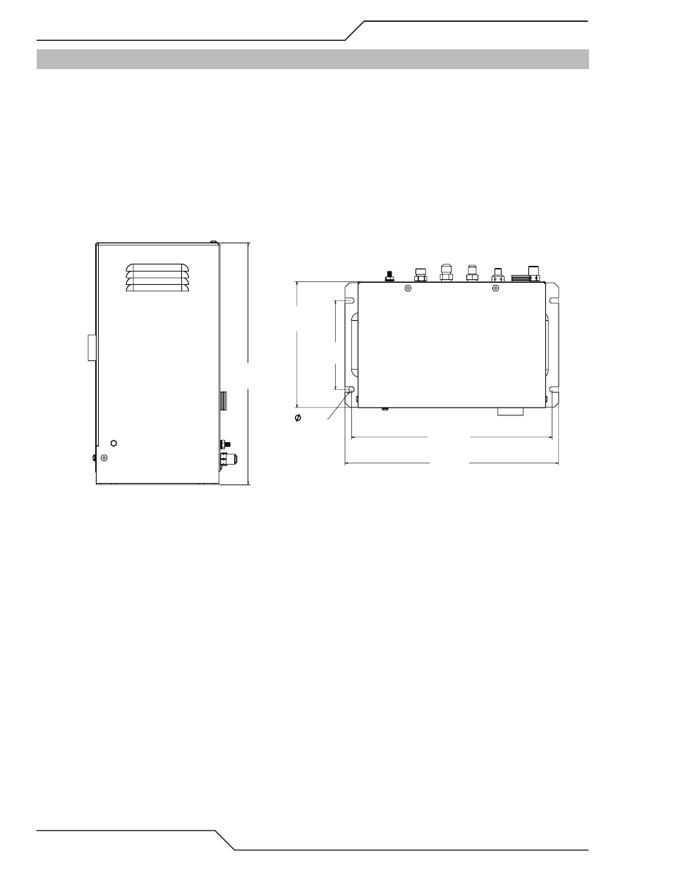
Mounting Dimensions
5.00 in
[127.0 mm]
7.08 in
[179.8 mm]
12.18 in
[309.4 mm]
11.44 in
[290.6 mm]
.30 in
[7.62 mm]
DMC-3000 Top
13.60 in
[345.6 mm]
DMC-3000 Profile
Art # A-09459