Mc2a mc2b, Fan1 – Tweco 400 Ultra-Cut XT Plasma Cutting System User Manual
Page 222
ULTRA-CUT 100 XT/200 XT/300 XT/400 XT
A-88
APPENDIX
Manual 0-5297
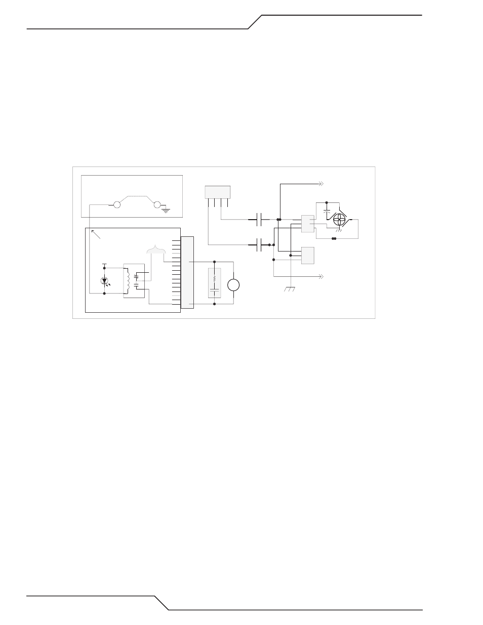
Troubleshooting:
1. Check for air blowing out of the unit. Remember, except for the AC 200 XT, the fans only run when CNC
START is applied and for 4 minutes after cutting, you may have to apply start again to restart the 4 minute
time. Fans may be forced on by jumping TP2 on the CCM I/O board to TP1 (ground).
a. If using the external HE400XT heat exchanger, optional for 300A, standard for 400A, check for air blow-
ing out of it. Note that the HE400XT fan, controlled by a thermal switch in the HE400XT, only runs if
the coolant is over 60 deg C and the internal fans are operating. With the 100 & 200A if it has 2 fans
make sure both fans are operating by checking for air both top and bottom of the opening. The fans are
difficult to see, perhaps you can use an inspection mirror. Be careful not to get the mirror or your hands
into the blades.
2. Fans are powered by 230 VAC. The 230 VAC for the fan(s) is switched by the MC2 control relay (except the
AC 200 XT where the fan(s) is powered directly from the T1 transformer at J13).
Art # 12311
1
2
3
4
5
6
7
8
9
10
11
12
13
14
15
16
J8
1
5
3
2
4
Fan Bias Control
K4
MC2
Fan Control
(160)
(161)
SA3
ARC_SUPPRESSOR
D24
24 VAC
Relay PCB
230 VAC from T1
MC2A
MC2B
To J70-2
To J70-3
(69)
(70)
(70)
(65A)
(70)
(69)
1
2
3
J73
(64A)
CHASSIS GND
1
2
3
J72
C4
FAN1
R
R
BK
BN
BL
1
2
3
4
J13
TP1
TP2
CCM I/O PCB
To test fan relay jump TP2 to TP1.
+24
J4-19
3. Check for 230 VAC at either of the fan connectors, J72 & J73. It may also be measured at the rear panel con-
nector J70 for the HE400XT fan.
a. If the fans are not getting 230 VAC, measure for 24 VAC on the coil of MC2. If present and the relay
contacts aren’t closed the relay is defective. Note, the coil is rectified so you won’t measure continuity
of even a good coil.
b. If 24 VAC is not on the MC2 coil check for D24 on the relay board being ON. If it’s on, the Relay board
should be providing the 24 VAC so if it’s not the Relay board must be defective.
c. If D24 is not on, measure on the CCM I/O board between TP2 and the common at TP1. It should be low,
near zero volts. If not the CCM is probably defective. Jumper TP2 (I/O board) to TP1. If the fans now
come on replace the CCM.
d. If jumping TP2 to TP1 does not turn the fans on then the Relay board or the 40 pin ribbon cable pin 19
is at fault.
404
Coolant System Not Ready
When power is applied to the system with External Plasma Enable satisfied and Plasma Power Supply Enabled
(switch on 2010 or TSC 3000), assuming there is enough coolant in the tank, after some initial tests taking about
15-20 seconds (see manual section 4 for details of the Start-Up Sequence) the pump will start. Coolant will be
pumped through the system. Flow is measured by the FS1 flow switch placed in the torch coolant return path
just before the radiator (see plumbing diagram). If the flow doesn’t reach at least 0.75 GPM (2.8 lpm) within
4 minutes it will set the 404 fault. The reason for the 4 minutes is a new dry system especially one with long
torch leads will take some time before the leads, hoses, radiator and cold plates are full of coolant. More coolant