02 system layout 100 - 200 amp – Tweco 400 Ultra-Cut XT Plasma Cutting System User Manual
Page 30
ULTRA-CUT 100 XT/200 XT/300 XT/400 XT
3-2
INSTALLATION
Manual 0-5297
Gas Supply
The customer must supply all gases and pressure regulators. Gases must be of high quality. Pressure regulators
must be double-stage and installed as close as possible to the gas console. Contaminated gas can cause one or more
of the following problems:
• Reduced cutting speed
• Poor cut quality
• Poor cutting precision
• Reduced consumables life.
• Oil or grease contamination from compressed or bottled air can cause fires in conjunction with oxygen.
Cooling System Requirements
Coolant must be added to the system on installation. The amount required varies with torch leads length.
Victor Thermal Dynamics recommends the use of its coolants 7-3580 and 7-3581 (for low temperatures).
Coolant Capabilities
Cat. Number and Mixture
Mixture
Protects To
7-3580 ‘Extra-Cool™’
25 / 75
10° F / -12° C
7-3581 ‘Ultra-Cool™’
50 / 50
-27° F / -33° C
7-3582 ‘Extreme Cool™’
Concentrate*
-76° F / -60° C
* For mixing with D-I Cool™ 7-3583
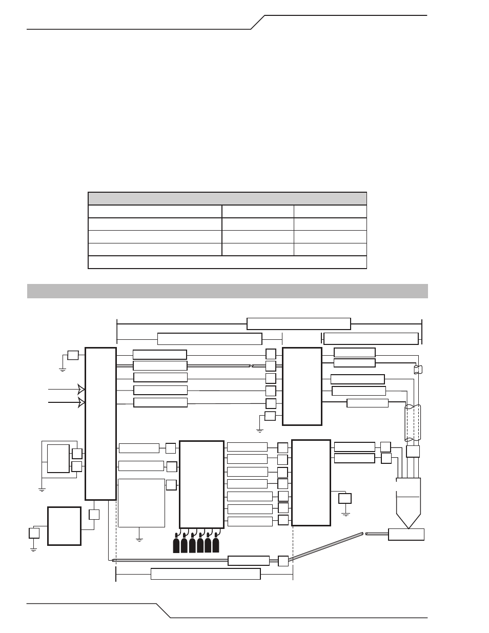
3.02 System Layout 100 - 200 Amp
Refer to section 3.08 and 3.10 for ground connections and ground cables.
Primary power
Work
CNC
Remote
Arc
Starter
Art # A-11995
Torch
Coolant Supply
Coolant Return
Control Cable
Pilot Return
Coolant Supply
Coolant Return
Plasma Gas
Shield Gas
Work Cable
DMC-3000
Gas
Console
Ultra-Cut
Power
Supply
DPC-3000
Gas
Control
Positioning Tube
Plasma Gas
Marking
Shield
Shield Gas
Negative
Pilot Return
Control Cable
100’ / 30.5 m Maximum Length
Shield
H
Q
R
U
S
A
B
C
D
E
P
K
L
O
I
J
G
175’ / 53.3 m Maximum Length
Preflow
Fiber Optic
L
Water Shield
T
125’ / 38.1 m Maximum Length
175’ / 53.3 m Maximum Length
Fiber Optic
Control Cable
F
Touch
Screen
Controller
V
W
F1
F1
F
F
Ground Cable
to PS Only
When DMC
Mounted On
Top Of PS
-If not - Earth-