SoundOff Signal LED3 Mini White Spot User Manual
Warning
To review our Limited Warranty Statement & Return Policy for this or any SoundOff Signal product please visit our website at www.soundoffsignal.com and select the “Warranty & Returns”
link along the left column of our home page. If you have questions regarding this product please contact Technical Services, Monday - Friday, 8 am to 5 pm at 1.800.338.7337, press #4 to
skip the automated message. Questions or comments that do not require immediate attention may be emailed to [email protected].
1.800.338.7337. / www.soundoffsignal.com / Thank you for trusting us with your safety!
OPERATION:
NOTE: The LED3 is a factory sealed unit
that CANNOT be serviced in the fi eld.
Any attempt to gain access to the LED3
unit will most likely cause permanent
damage and void its warranty.
IMPORTANT: DO NOT connect this
device to a strobe power supply.
OPERATING INSTRUCTIONS
1. Connect the LED3 BLACK wire to a
good, convenient ground.
2. Connect the LED3 RED wire to one
side of a user supplied on/off switch.
Connect the other side of the switch,
through a 5Amp fuse, to a source of
+Vdc power.
!
WARNING
This product contains high intensity LED devices.
To prevent eye damage, DO NOT stare into the
light beam at close range.
Please see reverse for
Technical Specifi cations
• DO NOT install this product or route any wires in the Air Bag Deployment Zone. Refer to your vehicle
Owner’s Manual for the location of any air bag deployment zones.
• DO NOT connect this device to a strobe power supply.
EL3SSCW 11.10
Important Information:
INSTALLATION:
IMPORTANT: DO NOT over tighten
mounting screws or nuts. This could
cause permanent damage to the light.
1. Locate fl at mounting location for the
LED3 Light.
2.
When the position of LED3 is
determined use paper template on
next page to drill hole locations.
Screw mounting holes should be
drilled using a 3/32” drill bit. Wire
entry holes should be drilled using a
1/4” drill bit.
3. Make electrical connections.
4. Using supplied #6 x 3/4” screws,
fasten LED3 to mounting surface. Be
sure not to overtighten screws as this
will cause hole in mounting surface
to strip out. Be sure that supplied
gasket is mounted between mounting
surface and LED3.
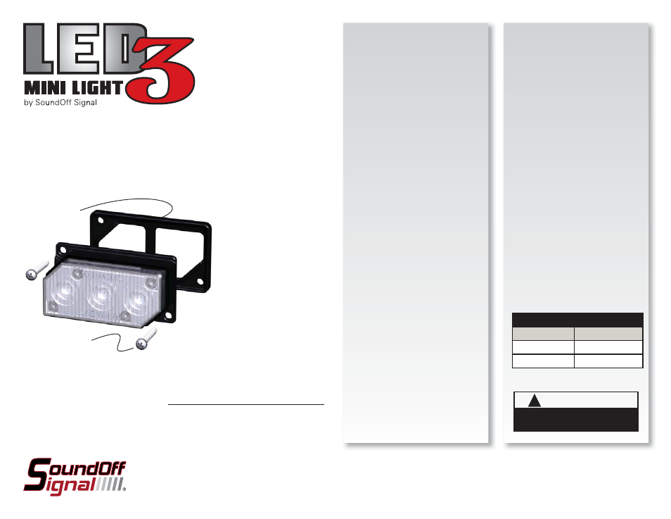
LED3 SURFACE MOUNT SPOTLIGHT
WIDE ANGLE OPTICS/STEADY BURN
EL3SSCW 10-16Vdc
EL3SS30CW 10-30Vdc
SUPPLIED GASKET
2x SUPPLIED #6x3/4”
SHEET METAL SCREWS
WIRE HOOK-UP TABLE
WIRE COLOR:
CONNECT TO:
RED
Power (+Vdc)
BLACK
Ground (-)