Installation and mounting – SoundOff Signal TrafficMaster Split Arrow Bar User Manual
Page 3
PROPER INSTALLATION COMBINED WITH OPERATOR
TRAINING IN THE PROPER USE OF EMERGENCY WARNING
DEVICES IS ESSENTIAL TO INSURE THE SAFETY OF
EMERGENCY PERSONNEL AND THE PUBLIC.
INSTALLATION AND MOUNTING
GENERAL
All devices should be mounted in accordance with the manufacturer’s in-
structions and securely fastened to vehicle elements of sufficient strength
to withstand the forces applied to the device.
WIRING
Do not use insulation displacement connectors (e.g. 3M Scotchlock type
connectors). Route wiring using grommets and sealant when passing
through compartment walls. High ambient temperatures (e.g. under-hood)
will significantly reduce the current carrying capacity of wires, fuses, and
circuit breakers. Use “SXL” type wire in engine compartment. Minimize
the number of splices to reduce voltage drop. All wiring should conform to
the minimum wire size and other recommendations of the manufacturer
and be protected from moving parts and hot surfaces. Looms, grommets,
cable ties, and similar installation hardware should be used to anchor and
protect all wiring.
Particular attention should be paid to the location and method of making
electrical connections and splices to protect these points from corrosion and
loss of conductivity. Ground terminations should only be made to substantial
chassis components, preferably directly to the vehicle battery.
The user should install a fuse sized to approximately 125% of the maximum
amp capacity in the supply line and each switched circuit to protect against
short circuits. For example, a 5 amp fuse should carry a maximum of 4
amps. Circuit breakers are very sensitive to high temperatures and will “false
trip” when mounted in hot environments or operated close to their capacity.
Fuses should be located as close to the vehicle power takeoff points as
possible and properly sized to protect the wiring devices.
Page 3
SPLIT ARROW LED TRAFFIC MASTER
SPLIT ARROW LED TRAFFIC MASTER Page 8
2. Route a 18 AWG wire attached to a reliable ground source. The vehicle’s
battery is the ideal source. NEVER FEED RADIO EQUIPMENT WITH
THE SAME GROUND CIRCUIT!!!! THIS CAN CAUSE ELECTROMAG-
NETIC INTERFERENCE WITH COMMUNICATION EQUIPMENT.
3. Route a 18 AWG wire attached to a power source (12 VDC). The vehicle’s
battery is again the ideal source. Place a 5 amp in-line blade type fuse
on this circuit. DO NOT USE FUSIBLE LINKS, CIRCUIT BREAKERS,
OR GLASS FUSES!!!
4. Attach the power and ground wire to the appropriate pins in the 2 pin
socket housing as shown in Figure 5.
5. Attach the wires from the two 5 wire harnesses into the appropriate 6
& 4 pin connectors as shown in Figure 5. BE SURE TO PLACE THE
PINS IN THE PROPER SEQUENCE!!!
6. With the control module switched to the “OFF “ position, plug the two
pin socket housing into the appropriate position in the rear of the control
module.
7. Mount the Control Module in the selected location.
The LED’s on the control box mimic the actions of the LED Traffic Master to
ensure proper selections and operation of the pattern chosen. If the LED
Traffic Master is not functioning correctly, call the
SoundOff Signal Tech-
nical Service Hotline at (800) 338-7337.
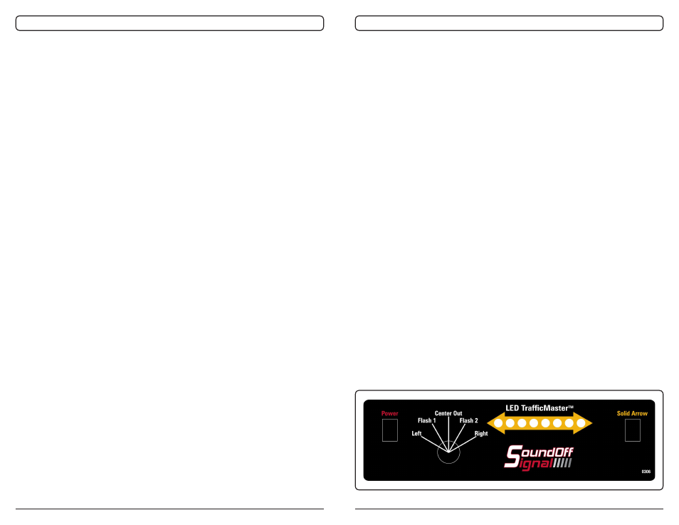
OPERATIONS
A five position rotary switch controls all of the LED Traffic Master’s primary
functions. The LED Traffic Master Control Module faceplate is shown in
Figure 6.
Figure 6. Control Module Faceplate