Permanent mounting, Rear deck and light bar mounting, Control module wiring – SoundOff Signal TrafficMaster Split Arrow Bar User Manual
Page 2
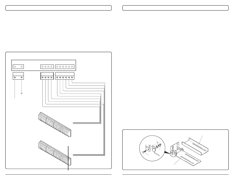
REAR VIEW OF CONTROL PANEL
GROUND
+ 12-24 Vdc
RED
BLACK
LIGHTBAR 2 - GREEN
LIGHTBAR 2 - YELLOW
LIGHTBAR 2 - BLUE
LIGHTBAR 2 - WHITE
LIGHTBAR 1 - WHITE
LIGHTBAR 1 - BLUE
LIGHTBAR 1 - YELLOW
LIGHTBAR 1 - GREEN
LIGHTBAR 2 - RED
LIGHTBAR 1 - RED
LIGHTBAR 1
LIGHTBAR 2
SPLIT ARROW LED TRAFFIC MASTER Page 4
FAILURE TO FOLLOW THE WARNINGS OR
INSTALLATION AND USER INSTRUCTIONS CAN RESULT
IN LOSS OF WARRANTY COVERAGE.
The following installation instructions provide direction for mounting the Traf-
fic Master to most light bar frames. Questions about a specific application
should be directed to the
Technical Service Hotline at (800) 338-7337.
PERMANENT MOUNTING
Prior to mounting, consideration should be given to cable location and lamp
replacement. The cable should exit the end cap on the driver’s side unless
otherwise specified. The lamp module replacement procedure is explained
in the Maintenance section of this manual.
REAR DECK AND LIGHT BAR MOUNTING
The Split Arrow LED Traffic Master should be mounted using the adjustable
“L” brackets which are provided. Refer to page 5 for specific mounting
instructions. In addition, note Figure 2, relating to mounting configurations
and STANDARD or OPTIONAL wiring specification. See page 7, Figure 5
for specific wiring.
1. If a light bar is already mounted on the vehicle, remove the light bar from
the vehicle roof and turn it upside down. Rest it on a cloth or some other
soft surface. It is not necessary to disconnect the wiring.
2. Select and assemble the adjustable “L” Bracket that fits your specific
needs. (See Fig. 1) Standard Bracket - recommended for rear deck and
light bar mounting. Heavy Duty Bracket - for use when Traffic Master will
be subject to high wind, vibration, and/or severe stress.
Page 7
SPLIT ARROW LED TRAFFIC MASTER
CONTROL MODULE WIRING
NOTE
DO NOT USE FUSIBLE LINKS, CIRCUIT BREAKERS
OR GLASS FUSES!!!
1. Choose the ideal mounting location for the Control Module. It fits into any
standard vehicle console that is designed to hold radio or other electronic
equipment. It also works well when mounted under the vehicle’s dash.
Figure 5. Standard and Optional Wiring Schematics
“STANDARD” LED TRAFFIC MASTER WIRING
Figure 1. “L” Bracket Assembly
Heavy Duty Bracket
LOCK WASHER
FLAT WASHER
NUT
BOLT
(5x15mm)
Standard Brack-