Electrical installation – SoundOff Signal Pinnacle LED User Manual
Page 10
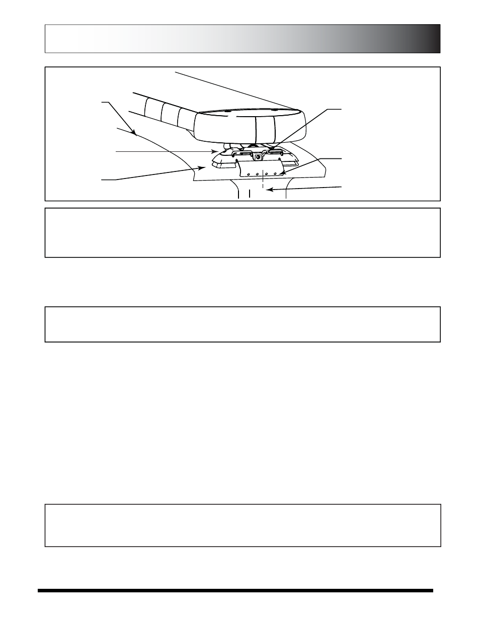
10. Tighten vehicle attachment brackets to roof by turning 5/32” Allen driver in COUNTER-CLOCKWISE ROTATION. Depending on
your desired height, you may need to cut down your allen wrench to fit between the bar and the mounting bracket. Or use a micro
drive gear wrench and 1/4” shank with 5/32” allen bit.
11. Route cables into vehicle. Use supplied rubber grommet in roof for sealing/protection of wires. It is recommended that silicone
be placed around grommet to ensure roof sealing.
12. Route cable down through the “B” pillar and towards switch panel. Refer to the instructions included with your switch for
switch wiring information.
WARNING - ROUTE WIRES ONLY IN LOCATIONS THAT ARE NOT SUBJECTED TO POTENTIAL WEAR.
MAKE SURE TO AVOID ROUTING WIRES IN THE DEPLOYMENT AREA OF YOUR AIR BAG. REFER TO
YOUR VEHICLE OWNER’S MANUAL FOR AIR BAG DEPLOYMENT ZONES
WARNING - ALL CUSTOMER SUPPLIED POWER WIRES CONNECTING TO THE POSITIVE (+) OR
NEGATIVE (-) BATTERY TERMINAL OR LOCAL CHASSIS GROUND (-) MUST BE SIZED TO SUPPLY AT
LEAST 125% OF THE MAXIMUM CURRENT AND PROPERLY FUSED AT THE POWER SOURCE WITH
APPROPRIATELY RATED FUSE.
Power Cable:
1. Route lightbar power cables as close to vehicles power source (battery) as possible.
ELECTRICAL INSTALLATION
Featured Highlights:
Mode Select: The PINNACLE Lightbar is equipped with 2 selectable pattern configuration modes via the Mode Select Input. Default
is Mode 1 where the input is floating, Mode 2 is in use when the input activated. This feature allows 2 complete sets of patterns to
be programmed into the Lightbar's non-volatile memory. Once programming configuration is complete, the Mode can be changed
“on-the-fly” by an activation switch.
Cruise Mode: Allows the user to program any Light Head Group(s) to “Glow” when this feature is activated.
Directional Arrow Built-in: If the lightbar was purchased with a directional arrow, the directional controller is built-in w/ 4 arrow
patterns for each direction and 9 warning patterns for warming functions.
ELECTRICAL INSTALLATION
LOCATION FOR MOUNTING
SCREWS TO ROOF
FEET MUST SIT
FLAT ON ROOF
TIGHTEN BRACKETS
TO ROOF BY COUNTER
CLOCKWISE ROTATION
REPRESENTS
VEHICLE ROOF
CENTER ABOUT “B” PILLAR
FRONT-BACK
TILT ADJUSTMENT
SCREWS
WARNING - CARE MUST BE TAKEN WHEN DRILLING THROUGH THE ROOF OF THE VEHICLE NOT TO
DRILL INTO ANY EXISTING WIRING AND NOT TO DRILL THROUGH THE HEADLINER OR SUPPORT
MEMBERS OF THE VEHICLE. CHECK BOTH SIDES OF THE MOUNTING SERVICE PRIOR TO DRILLING.
DE-BURR ANY HOLES AND REMOVE ANY METAL SHARDS OR REMNANTS. INSTALL GROMMETS
INTO ALL WIRE PASSAGE HOLES.
FIGURE 3
Page 10