Flowrite ii maintenance – Powers 593 Series Flowrite II Heavy Duty Bronze Globe Control Valves - Heavy Duty Bronze User Manual
Page 9
TI593UBS
Page 9
FLOWRITE II MAINTENANCE
PACKING REPLACEMENT
The steam service Flowrite II uses spring loaded glass Teflon
®
V-Rings
or Split Ring Graphite. This packing is self lubricating; additional
lubricant is not recommended. Liquid service Flowrite II valves use EP
spring loaded V-ring packing, on which silicone lubricant (part
number 590-165A) is only for installation. For the proper packing kit
see Packing Kit Chart in Appendix.
1. The stem surface must be smooth with no roughness or
imperfections, which can cut, nick, or stretch packing pieces.
Replace stem if imperfections are present.
2. Do not lubricate the bonnet chamber for steam service
packing and EP liquid service packing. Steam service
packing is self lubricating.
3. Protect the beveled or O-ring mating surfaces of valve body and
bonnet. Damaged or nicked bevel or O-ring surface will cause the
valve to leak.
REPACKING PROCEDURE
1. Shut off controlled medium passing through the valve
(steam, water, or other liquid) and remove control signal to
the actuator.
2. Remove bonnet locknut; turn counterclockwise, (Figure 1).
3. Hold the actuator stem in place, loosen the stem locknuts;
turn locknuts counterclockwise. (Figure 2).
4. Place masking tape on valve stem to indicate how far
actuator stem threads onto valve stem.
5. Hold actuator stem and turn valve stem counterclockwise using
locknuts until stems are separated.
6. Remove actuator from valve assembly.
7. Remove packing gland nut. Remove bonnet from body and
push out stem assembly for access to packing.
8. Remove old packing and replace with new parts in packing
kit (see table for kit part numbers). If using EP V-ring
packing, lubricate with silicone grease,
(part number 590-165A).
9. Reassemble valve in reverse sequence.
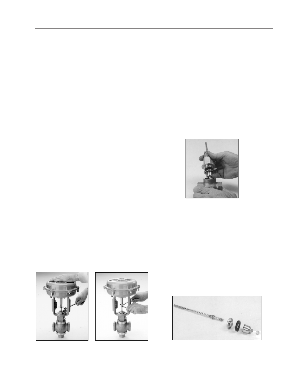
DISC REPLACEMENT
1. Shut off controlled medium passing through the valve
(steam, water, or other liquid) and remove control signal to
the actuator.
2. Remove bonnet locknut (turn counterclockwise). Hold the
actuator stem in place and loosen the stem in place and
loosen the stem locknuts (turn locknuts counterclockwise).
Place masking tape on valve stem to indicate how far
actuator stem threads onto valve stem. Hold actuator stem
and turn valve stem counterclockwise using locknuts until
stems are separated. Remove actuator from valve assembly.
3. Unscrew the bonnet (turn counterclockwise) and pull
assembly out of the valve body.
4. Remove locknut, throttling plug, and old disc from
stem assembly.
5. Replace with new disc and reassemble in reverse order.
See Figure 3.
SEAT REPLACEMENT
Note: Seats are not replaceable on all valves. If seats are damaged, a
new valve body may be required.
Valve
Replaceable
VE
Yes (special tool required)
SD
No
SS
Yes (special tool required)
WM
No
DB
No
Figure 2
Figure 1
Figure 3
Stem Assembly