Kenco Engineering SmartSonic Transmitter (Remote) User Manual
Page 8
Page 8
CALIBRATION
This section explains how to set up and calibrate the SmartSonic for accurate measurement monitoring using the basic
menu options. SmartSonic is supplied with preprogrammed default settings, making it ready for immediate operation.
Measurement readings are displayed on the default screen as soon as the unit is powered on. It is recommended that
you replace the default tank height value with the actual tank height, as described later in this section.
Display / Keypad
The LCD display screen functioning in “Normal” mode provides continuously updated measurement readings. This
display is also used to view the program menus, options, settings, and data values. These are accessed by using the
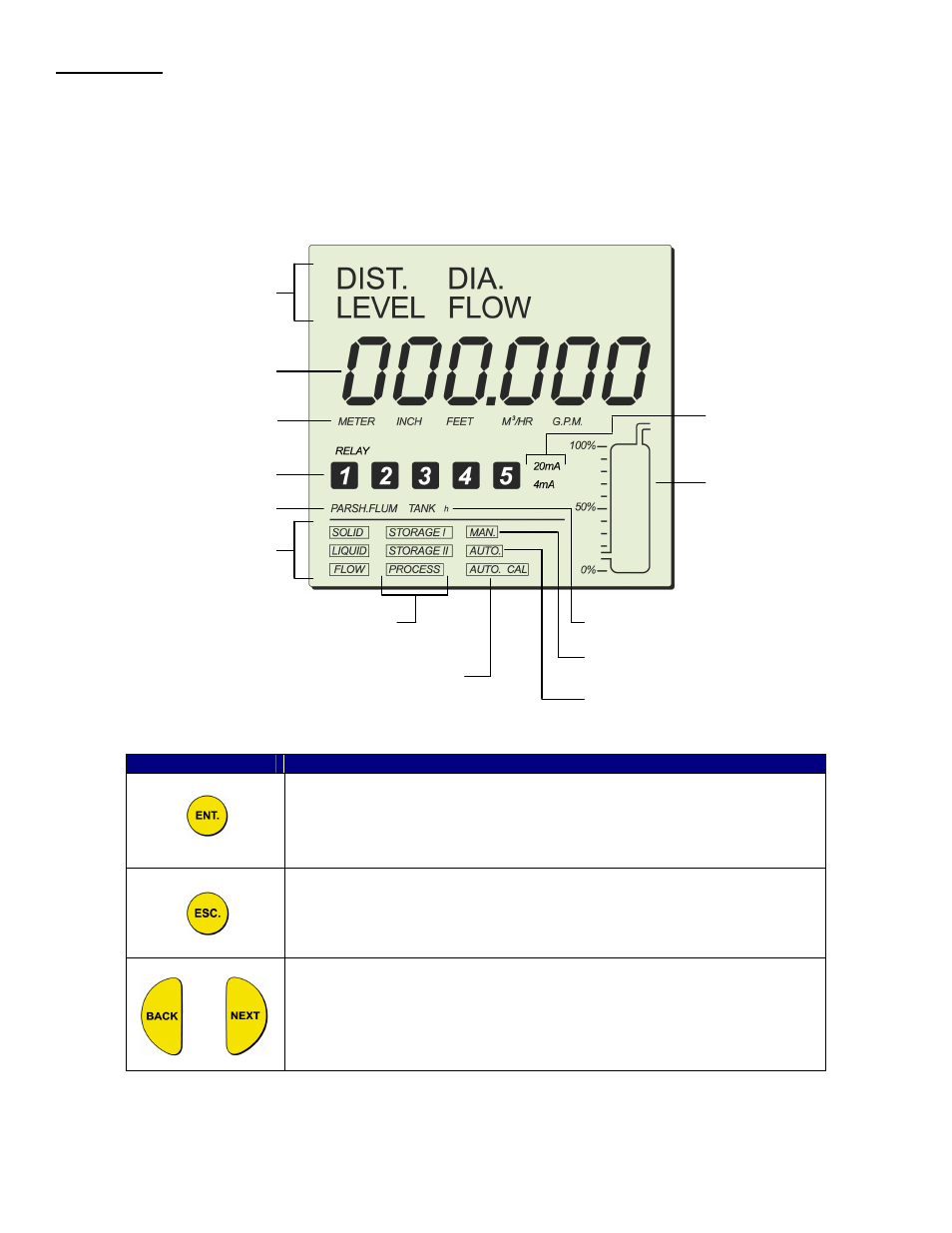
keypad. The picture below shows the display of the SmartSonic:
The keypad buttons are used to perform various operations, summarized in the following table
Button
Uses Include:
• Accessing the program menu (when pressed simultaneously with “ESC.”
• Accessing a function within a menu, enabling you to make modifications
• Moving from left to right between displayed digits.
• Saving changes to data.
• Accessing the program menu (when pressed simultaneously with “ENT.”
• Moving from right to left between displayed digits.
• Returns you to the previous function (without saving changes), or back to
the default screen
or
• Moving to the next/previous function within a menu.
• Scrolling through or back data values in programs.
NOTE: Within some programs, the digits in the display can be individually modified. This is indicated by a flashing digit.
In this case the
ENT and ESC buttons are used to move between digits. The BACK and NEXT buttons are used to
change the value of the flashing digit.
Indication modes
Numerical area
Measurement
units
Relays
Flow
measurements
Application types
20 mA/4 mA
levels
Tank graphic
Tank height
Sensor offset
Scan distance
mode indicator
Operation
modes
Clear scan distance